Vacuum dust collector

A technology for vacuum cleaners and dust collection buckets, which is applied in the directions of vacuum cleaners, cleaning equipment, household appliances, etc., can solve environmental pollution, the exhaust filter 14 and the exhaust port 14 cannot be tightly connected, and the exhaust filter 14 is not easy. Disassembly and other problems, to achieve the effect of prolonging the service life, reducing the air temperature, and the best vacuuming effect

Inactive Publication Date: 2010-06-09
LG ELECTRONICS (TIANJIN) APPLIANCES CO LTD
View PDF4 Cites 5 Cited by
  • Summary
  • Abstract
  • Description
  • Claims
  • Application Information

AI Technical Summary

Problems solved by technology

[0011] However, in view of the fact that the external air is inhaled from the suction port 20, after entering the dust bag 11, various foreign objects and larger dust are collected in the dust bag 11, and then the air containing fine dust flows into the space where the suction air flow generating components are arranged. (that is, the space containing the motor 12 and the rotating fan 13), most of the air flows through the motor 12 with the shortest distance in a straight line, and then is discharged to the outside of the vacuum cleaner body 10 through the exhaust port 14, because the motor 12 generates heat when it is working. Thereby the air passing through the exhaust port 14 is a hot air flow, and the hot air flow directly passes through the exhaust port 14 with the shortest distance in a straight line after flowing through the motor, and the air volume is relatively large, so the exhaust filter 15 at the exhaust port 14 is provided Under the action of long-term hot air flow, it is easy to cause the exhaust filter 14 to be heated and deformed, causing the exhaust filter 14 and the exhaust port 14 to be unable to be tightly connected, and there is a certain gap between them, containing fine dust The air leaks out from the gap, pollutes the environment outside the vacuum cleaner, and seriously affects the dust collection effect of the vacuum cleaner
In addition, the exhaust filter 14 is deformed by heat, so that the exhaust filter 14 is not easy to disassemble, and it is difficult for users to maintain

Method used


Image

  • Vacuum dust collector
  • Vacuum dust collector
  • Vacuum dust collector

Examples


Embodiment Construction

[0030] In order to enable those skilled in the art to better understand the solution of the present invention, the present invention will be further described in detail below in conjunction with the accompanying drawings and embodiments.

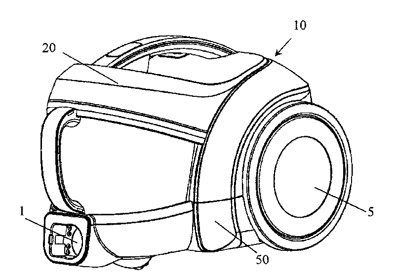
[0031] image 3 It is a three-dimensional schematic diagram of a vacuum cleaner provided by the present invention, Figure 4 It is a three-dimensional explosion diagram of a vacuum cleaner provided by the present invention, Figure 5 It is an exploded schematic diagram of a motor assembly in a vacuum cleaner provided by the present invention, Figure 6 It is a schematic diagram of the motor compartment and the air path included in the motor assembly of a vacuum cleaner provided by the present invention.

[0032] see Figure 3 to Figure 6 A vacuum cleaner provided by the present invention includes: an upper cover assembly 20 located on the upper part of the vacuum cleaner and a bottom case assembly 50 located at the bottom of the vacuum cl...


PUM


Abstract

The invention discloses a vacuum dust collector which comprises an upper cover component and a bottom shell component, wherein the space surrounded by the upper cover component and the bottom shell component is internally provided with a dust collecting barrel and a motor component in parallel; the right side of the motor component is provided with a plurality of motor air inlet holes; the bottom of the motor component is provided with a plurality of motor air outlet holes; an air way channel is formed between the bottom of the motor component and the bottom shell component; the air way channel is communicated with an exhaust hole and the motor air outlet holes; the left side of the motor component is provided with the exhaust hole; the right side at the bottom of the bottom shell component is provided with an air inlet hole; and the air inlet hole is communicated with the motor air inlet holes by the dust collecting barrel. The vacuum dust collector leads the air temperature at the exhaust hole of the dust collector to be greatly reduced, avoids an air filtering component arranged at the exhaust hole being deformed caused by long-term heating, prolongs the service life of the air filtering component arranged at the exhaust hole of the dust collector, and ensuring the dust collector to achieve better dust collecting effect.

Description

technical field [0001] The invention relates to the technical field of mechanical dust removal, in particular to a vacuum cleaner. Background technique [0002] Generally, a vacuum cleaner is a device that uses a vacuum to generate suction to inhale air, make the air flow through various filters, filter foreign objects in the air, and clean the room. [0003] Generally speaking, a vacuum cleaner mainly includes a suction device and a suction pipeline. The suction device mainly formed by a motor and a fan is arranged in the body. The suction pipeline includes a suction head and a suction pipe. The suction head has a downward opening. The suction port communicates with the air inlet of the fan inside the body through the telescopic pipe and the flexible pipe of the suction pipe. When the vacuum cleaner is running, the motor drives the impeller of the fan to rotate at a high speed, exhausting the air in the vacuum cleaner, forming an instantaneous vacuum in the vacuum cleaner,...

Claims


Application Information

Patent Timeline
Patent Type & Authority Applications(China)
IPC IPC(8): A47L5/00
Inventor 刘斌
Owner LG ELECTRONICS (TIANJIN) APPLIANCES CO LTD
Why Eureka
Try Eureka