High-voltage vacuum breaker

A vacuum circuit breaker, high-voltage technology, applied in high-voltage air circuit breakers, high-voltage/high-current switches, circuits, etc., can solve the problems of contact surface burnout, unfavorable post-open phase, unfavorable breaking inductance, etc., to achieve Reduce the opening speed, reduce shaking, and facilitate the effect of arc extinguishing

Inactive Publication Date: 2009-09-09
BEIJING HUADONG SENYUAN ELECTRIC
View PDF1 Cites 8 Cited by
  • Summary
  • Abstract
  • Description
  • Claims
  • Application Information

AI Technical Summary

Problems solved by technology

from Figure 7 It can be clearly seen that it is not conducive to the breaking of the subsequent opening phase. a is the opening characteristic curve of the known technology. When the contact movement time is t1=1-3ms, the separation distance is only s1 =0.5mm, the characteristic curve is in a gentle transition state, and the surface of the contact is severely burned when the switch is opened
At the same time, the existing circuit breaker can only contact the upper opening buffer after the two contacts are separated by about 6mm, and the action stroke of the piston rod of the opening buffer is generally about 18mm, resulting in a high opening speed and a long time for opening to the end. Short, usually 8 ~ 12ms, resulting in too large opening distance when the arc is extinguished by the rear opening phase, the current interception level is high, which is not conducive to breaking the small current of the inductance; when the gate is opened to the bottom, the mechanical vibration area overlaps with the arc extinguishing area of ​​the rear opening phase, It is unfavorable to the arc extinguishing of the post-opening phase, especially for single-phase breaking, which is an important reason why the circuit breaker cannot obtain good opening characteristics

Method used


Image

  • High-voltage vacuum breaker
  • High-voltage vacuum breaker
  • High-voltage vacuum breaker

Examples


Embodiment Construction

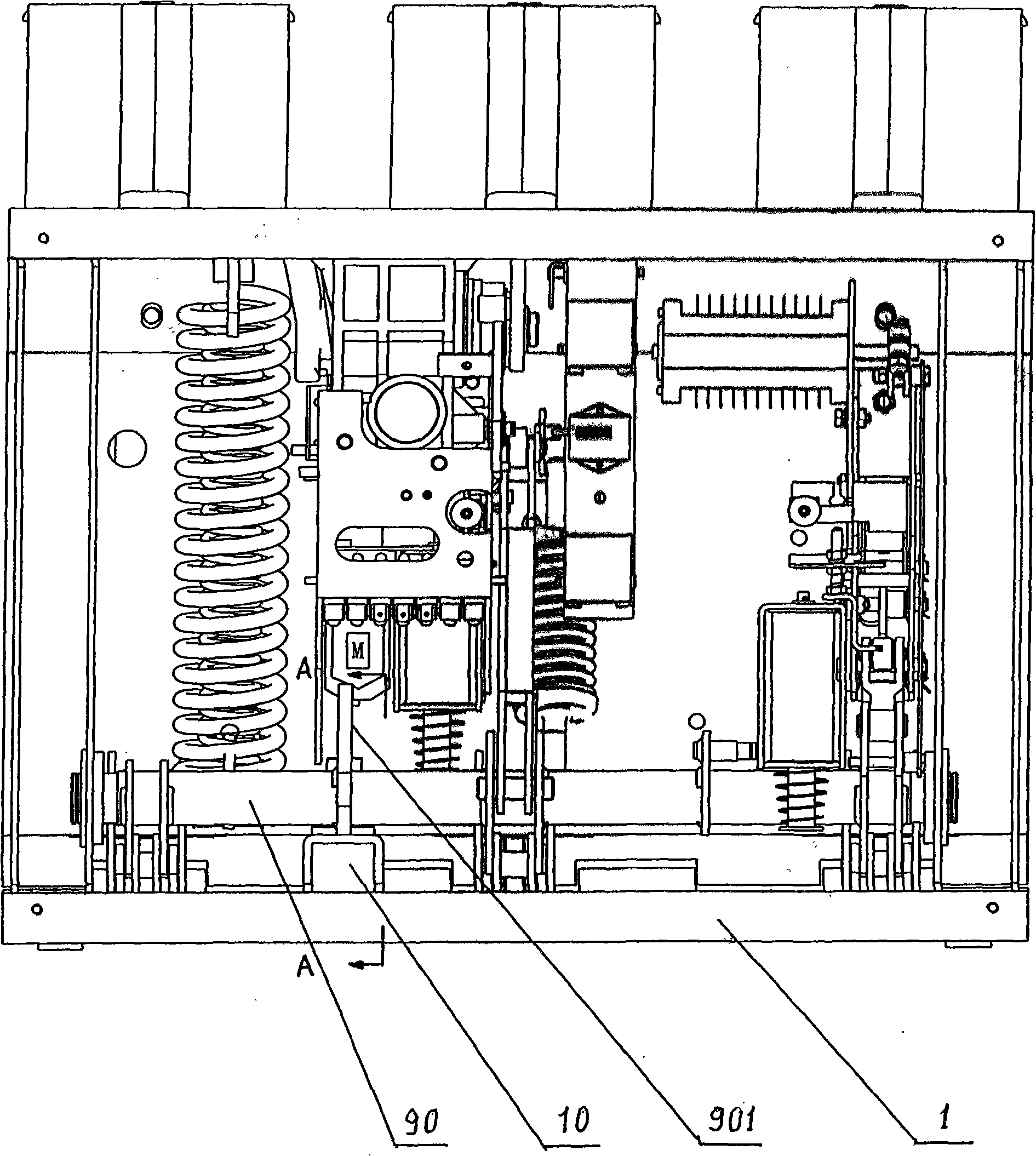
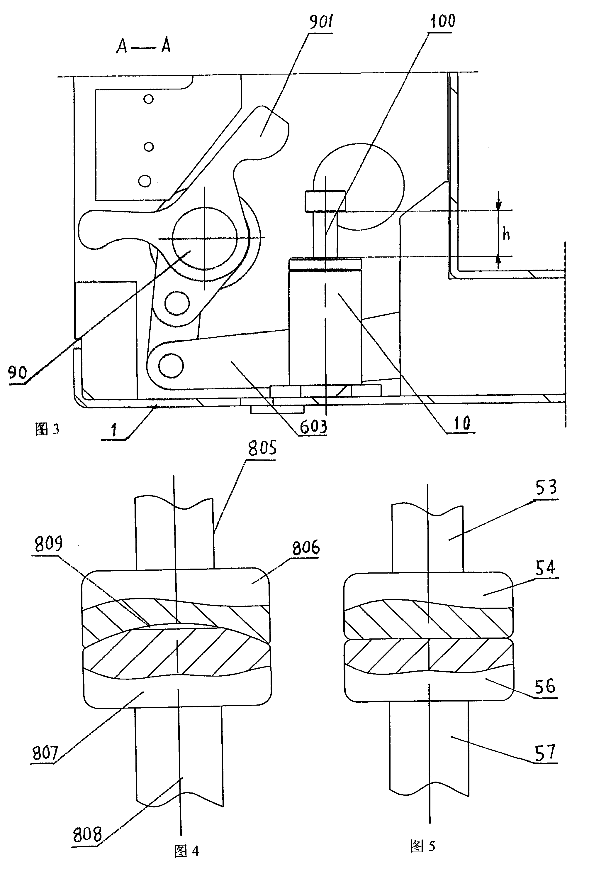
[0023] refer to figure 1 and figure 2 , The high-voltage vacuum circuit breaker of the present invention includes a frame 1 , a main shaft 90 , an operating mechanism 60 and its four-bar linkage assembly 603 , a main circuit 80 and an opening buffer 10 . The main shaft 90 is connected to one end of the four-bar linkage assembly 603 , and the other end of the four-bar linkage assembly 603 is connected to the main circuit 80 .

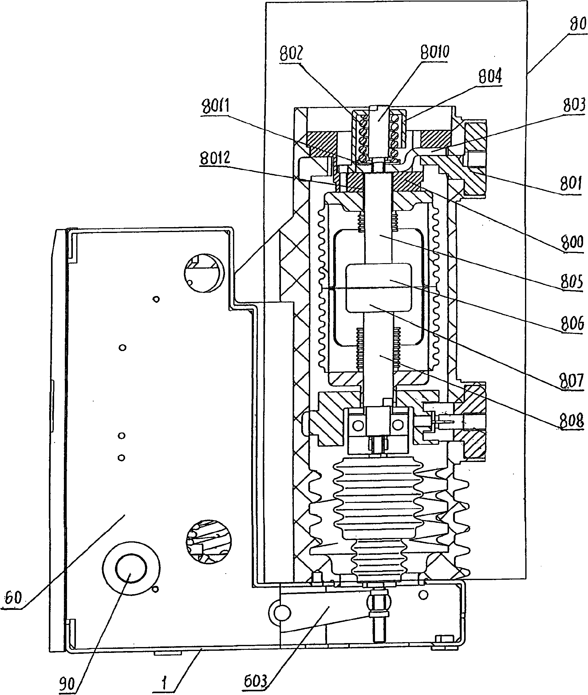
[0024] The main circuit 80 includes an upper bracket 800, an upper outgoing line 801, a soft connection 803, a contact spring 802, a spring cover 804 for a built-in contact spring 802, a contact spring seat 8011, an upper conductive rod 805, an upper contact 806, a lower The contact 807 , the lower conductive rod 808 and the guide rod 8010 located in the contact spring 802 . The upper conductive rod 805 passes through the through hole of the upper bracket 800 , and an insulating ring 8012 is sleeved between the upper conductive rod 805 and the throug...


PUM


Abstract

The invention relates to a high-voltage vacuum breaker which consists of a framework, a principal shaft, an operating mechanism and a four-connecting-rod assembly thereof, a principal loop and a separating brake buffer. The principal loop is provided with a spring cover and a guide bar of a contact spring; contact surface of the upper and lower contacts are changed into spherical contact; and actuating length of the piston rod of the separating brake buffer is 21-24mm. The high-voltage vacuum breaker of the invention has the advantages that guide length of the upper conducting rod is extended; swing of the upper contact and the upper conducting rod, namely, influence of axial and side force is reduced; and axial characteristic of motion is improved. Contact surface of the upper and lower contacts are changed into spherical contact, thereby increasing contact surface to facilitate arc blowout when the brake is separated. Actuating length of the piston rod of the separating brake buffer is changed, so as to contact connecting lever of the principal shaft with the upper separating brake buffer when the two contacts are separated for 2mm. Therefore, the high-voltage vacuum breaker reduces brake separating speed and limits separate-to-bottom time to approximately 20ms, so as to obtain stable brake separating characteristic and ensure reliability of breaking current of the high-voltage vacuum breaker. Therefore, the brake separation motion better satisfies requirements of the high-voltage vacuum breaker on electric property.

Description

technical field [0001] The invention relates to the field of high-voltage switches, in particular to a high-voltage vacuum circuit breaker. Background technique [0002] In the patent 200720128983.2 "A Main Circuit Structure of a High-Voltage Vacuum Circuit Breaker", such as Figure 6 As shown, the main circuit includes outlet wire 51, contact spring 59, vacuum interrupter 52, upper bellows 582, upper conductive rod 53, upper contact 54, lower contact 56, lower bellows 581 and lower conductive rod 57, The vacuum interrupter 52 is provided with a magnetic shell 55, the magnetic shell 55 is fixed on the outgoing line 51, the upper end of the contact spring 59 is fixed on the outgoing line 51, the lower end is fixed on the upper end of the upper conductive rod 53, and the upper contact 54 is fixed on the upper conductive rod. The lower end of the rod 53, the lower contact 56 is fixed on the upper end of the lower conductive rod 57, the upper bellows 582 is arranged on the upper...

Claims


Application Information

Patent Timeline
Patent Type & Authority Applications(China)
IPC IPC(8): H01H33/66H01H33/664H01H33/666
Inventor 聂崇志黄创国史书轩
Owner BEIJING HUADONG SENYUAN ELECTRIC
Why Eureka
Try Eureka