Glass ribbon producing apparatus and process for producing the same

A technology for a manufacturing device and a manufacturing method, which is applied to a glass ribbon manufacturing device and its manufacturing field, can solve problems such as damage, breakage, and cutting of the glass ribbon, and achieve the effect of preventing shape deformation.

Active Publication Date: 2009-09-09
NIPPON ELECTRIC GLASS CO LTD
View PDF2 Cites 9 Cited by
  • Summary
  • Abstract
  • Description
  • Claims
  • Application Information

AI Technical Summary

Problems solved by technology

Therefore, the disturbance of the attitude|position of a glass ribbon cannot be restrained by this cooler
In addition, as shown in the document, the glass ribbon is pinched by a plurality of rollers (stretching rollers) arranged at regular intervals along the conveying direction. Although it is considered to limit the disorder of the attitude of the glass ribbon, in this case, because the rollers Since the glass ribbon is pinched, there is a risk of causing fatal problems such as damage or cuts to the glass ribbon by the roller.
In addition, the rollers pinching the glass ribbon are in contact with the middle portion in the width direction of the glass ribbon, and the same problem as that of the above-mentioned Patent Document 1 occurs.

Method used


Image

  • Glass ribbon producing apparatus and process for producing the same
  • Glass ribbon producing apparatus and process for producing the same

Examples


Embodiment Construction

[0042] Embodiments of the present invention will be described below with reference to the drawings.

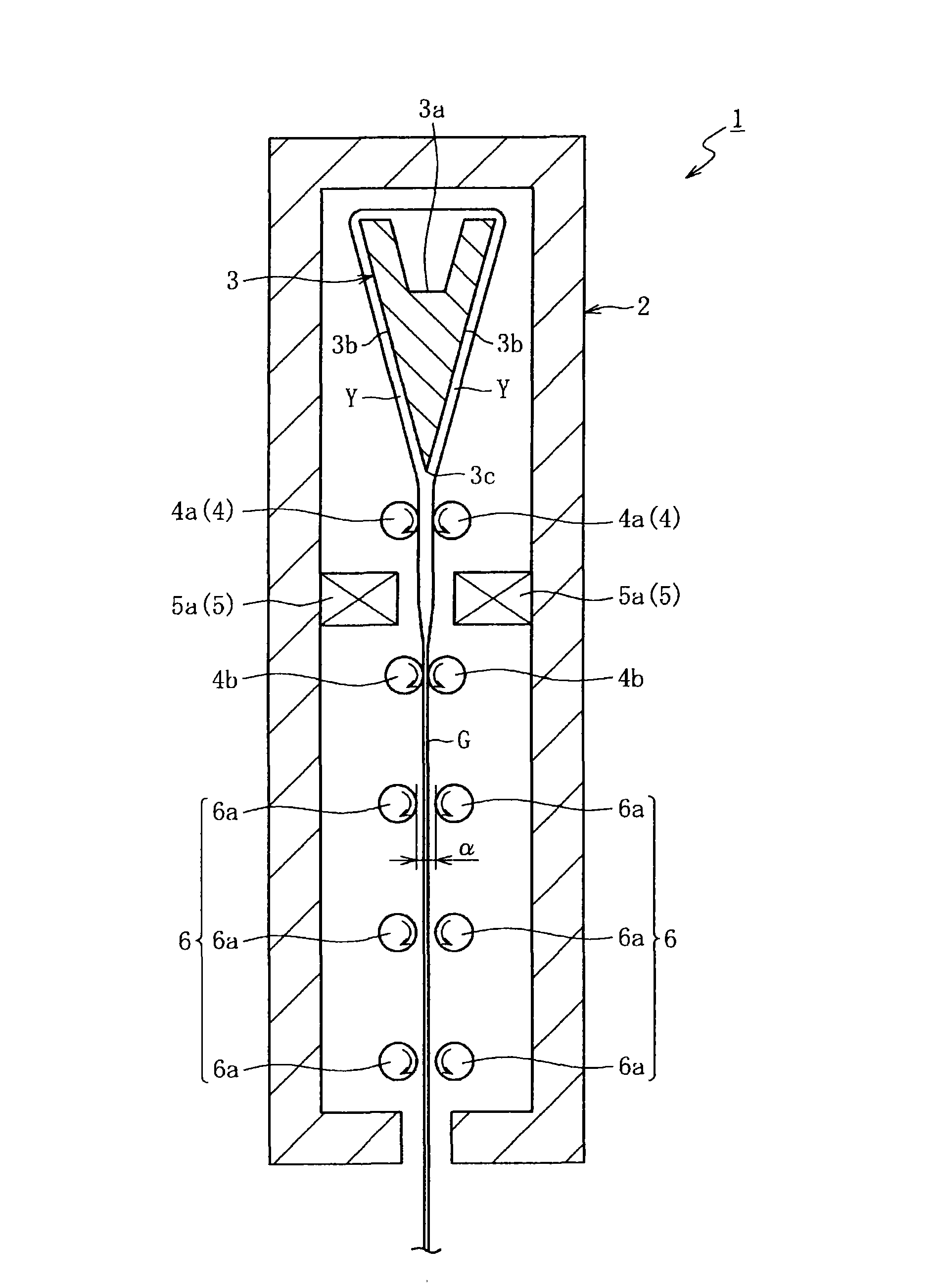
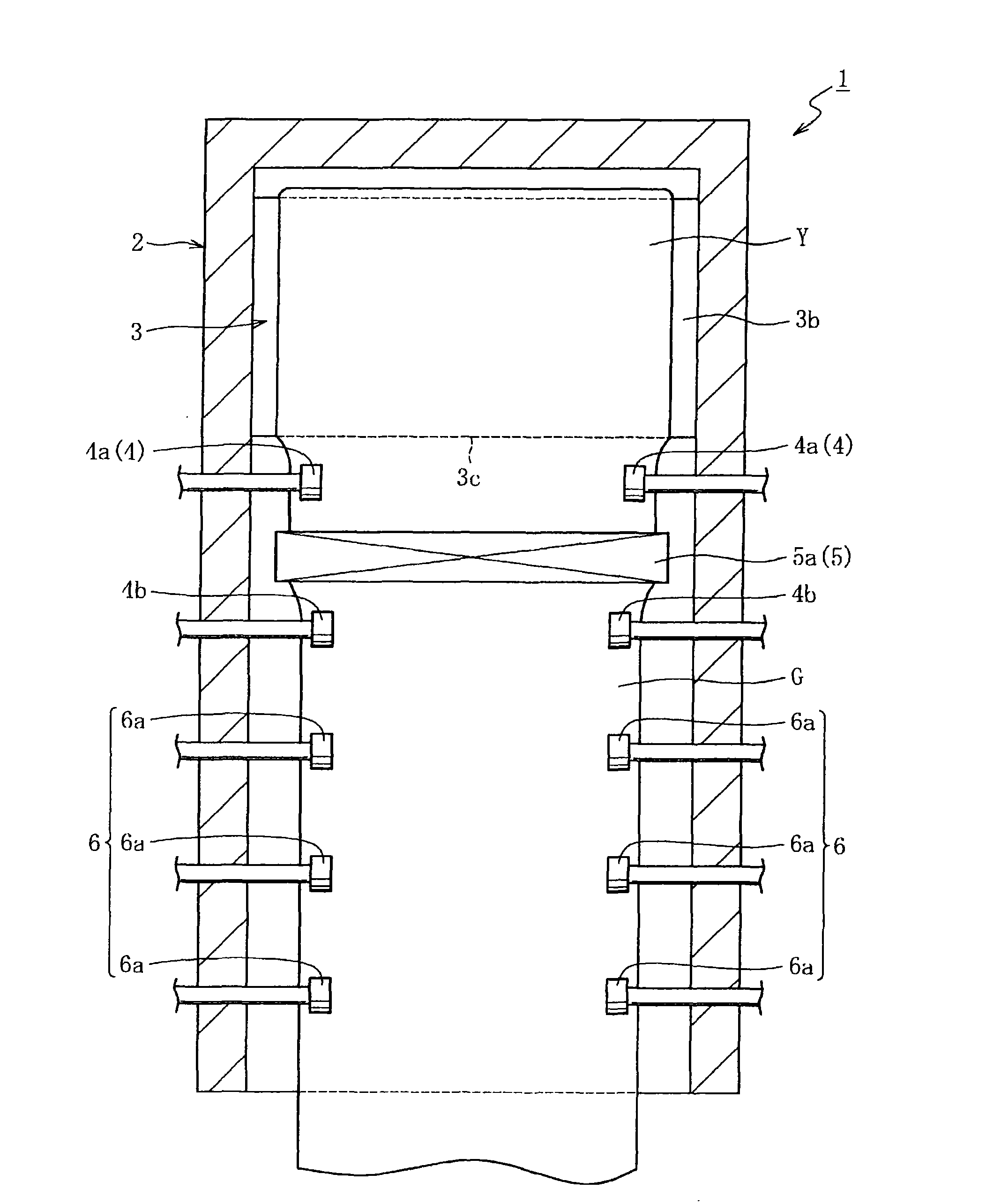
[0043] figure 1 It is a schematic vertical side view schematically showing the internal state of the glass ribbon manufacturing apparatus which concerns on one Embodiment of this invention. figure 2 is a schematic longitudinal front view schematically showing the internal state of the manufacturing apparatus. As shown in each figure, the manufacturing apparatus 1 has a molded body 3, a cooling mechanism 4, a reheating mechanism 5, and a guide mechanism 6 sequentially from above inside a furnace 2 made of refractory tiles.

[0044] The forming body 3 is a member having a wedge-shaped cross section and having an overflow groove 3a at the top, and the molten glass Y supplied to the overflow groove 3a overflows from the top, and the overflowing molten glass Y flows down along both side surfaces 3b of the forming body 3 On the other hand, it fuses at the lower end part 3c of the...


PUM

PropertyMeasurementUnit
thicknessaaaaaaaaaa

Abstract

The invention provides a glass ribbon producing apparatus (1) adapted to feed molten glass (Y) to molding member (3) and to cause the molten glass (Y) to flow downward from the molding member (3) so as to form sheetlike glass ribbon (G), comprising guide means (6) disposed on a transport route for the glass ribbon (G) flowing downward, which guide means (6) has a gap of dimension larger than the sheet thickness at across-the-width both ends in the direction of thickness of the glass ribbon (G) and guides within the bound of the gap only the across-the-width both ends of the glass ribbon (G).

Description

technical field [0001] The present invention relates to a glass ribbon manufacturing apparatus and a manufacturing method thereof. Specifically, the present invention relates to improvement of a glass ribbon manufacturing technique by a so-called down-draw method in which a glass ribbon is formed by flowing molten glass down from the forming body. Background technique [0002] As is well known, in the manufacture of glass sheets, the so-called down-draw method in which molten glass is flowed down from a molded body to form a glass ribbon serving as an original sheet of a glass sheet has become a recognized method, and the overflow down-draw method (melting method) can be cited as a representative of the down-draw method. or the slit pull down method. The former overflow down-draw method is to make the molten glass continuously supplied to the molded body having a wedge-shaped cross-sectional shape flow down from the top of the molded body along both sides, thereby making it ...

Claims


Application Information

Patent Timeline
Patent Type & Authority Applications(China)
IPC IPC(8): C03B17/06
CPCC03B17/064C03B17/068C03B17/06
Inventor 笘本雅博织田英孝
Owner NIPPON ELECTRIC GLASS CO LTD
Why Eureka
Try Eureka