Square stirrup discharge device

A technology of unloading device and stirrup, which is applied in the direction of loading/unloading, transportation and packaging, wire netting, etc. It can solve the problems of low efficiency of manual unloading, labor waste, shape deformation, and messy stacking, etc., and achieve good overall structural strength, Short length and material saving effect

Active Publication Date: 2019-03-12
CHINA METALLURGICAL CONSTR ENG GRP
View PDF5 Cites 0 Cited by
  • Summary
  • Abstract
  • Description
  • Claims
  • Application Information

AI Technical Summary

Problems solved by technology

[0003] In view of the above-mentioned deficiencies in the prior art, the technical problem to be solved by the present invention is to provide a square stirrup unloading device, which avoids the problem of low manual unloading efficiency and waste of labor, and avoids the formed square stirrups from freely falling to the ground and causing stacking. Messy, easy to cause damage to the appearance and shape deformation, and achieve the effect of automatically accepting the formed square stirrups at the preset position, and transporting them to the preset unloading position for stable unloading

Method used


Image

  • Square stirrup discharge device
  • Square stirrup discharge device
  • Square stirrup discharge device

Examples


Embodiment Construction

[0046] The specific implementation manners of the present invention will be further described in detail below in conjunction with the accompanying drawings.

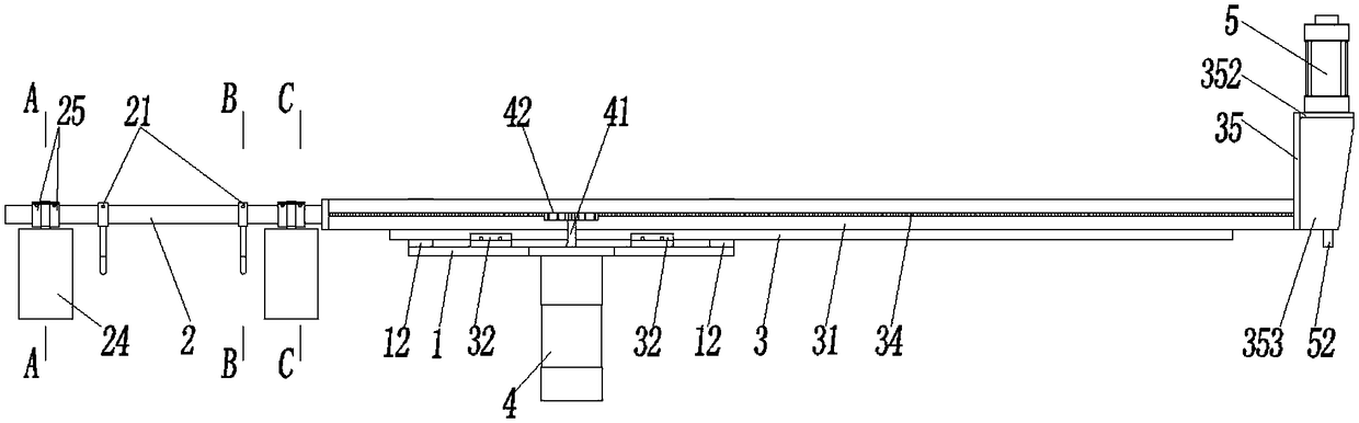
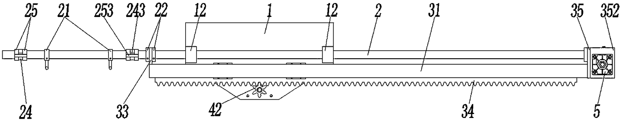
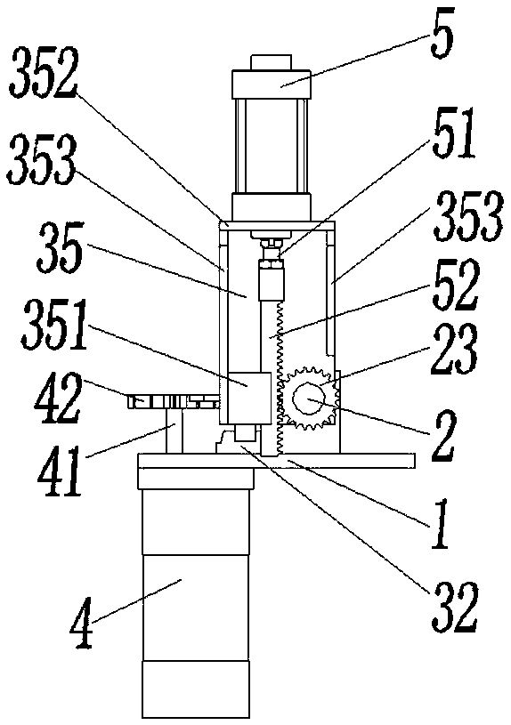
[0047] see figure 1 , Image 6 , a square stirrup unloading device, comprising a bottom plate 1, two shaft seats 12 are arranged at intervals on the bottom plate 1, and a horizontal unloading shaft 2 is installed in the two shaft seats 12 which are rotatable and can move along their own axial direction, One end of the blanking shaft 2 is provided with two blanking hooks 21 at intervals for receiving square stirrups. The blanking hook 21 includes an integrated hook portion 211 and an annular portion I212, and is sleeved on the blanking shaft 2 through the annular portion I212 so that the blanking hook 21 can move along the blanking shaft 2. Axially slide the distance between the blanking hooks 21 to adjust the distance between the hooks 21. A threaded through hole I213 is provided on the ring part I212 along its radial ...


PUM


Abstract

The invention relates to a square stirrup discharging device which comprises a baseplate, wherein two shaft seats are arranged on the baseplate; shaft holes which are positioned in one and the same straight line are correspondingly formed in the shaft seats; an unloading shaft penetrates through the shaft holes and is rotatably mounted on the shaft seats; at least two unloading hooks are arrangedat one end of the unloading shaft in a spacing manner and used for bearing square stirrups; an axial motion driving mechanism and a rotation driving mechanism are connected with the unloading shaft; the axial motion driving mechanism is used for driving the unloading shaft to move along the axial direction of the shaft holes; the rotation driving mechanism is used for driving the unloading shaft to rotate. By adoption of the square stirrup discharging device provided by the invention, the formed square stirrups can be steadily borne at a preset bearing position and conveyed to a preset discharging position for being stably discharged, thereby achieving the high degree of automation, reducing the labor cost, and improving the discharging efficiency; and through the cooperation with a synchronously-distributed accommodating box, the square stirrups can correctly fall into the preset accommodating box below in a vertical state, thereby solving the problems that the square stirrups are disorderly stacked, the appearances of the square stirrups are easy to damage, and the shape deformation is caused.

Description

technical field [0001] The invention belongs to the technical field of wire rod processing or treatment, and in particular relates to a square stirrup unloading device. Background technique [0002] In the steel frame structure of a building, in addition to the linear main reinforcement, square stirrups are also required to connect several main reinforcements to form a steel skeleton. The connection between the stirrup and the main reinforcement can be binding or welding. Square stirrups need to be formed by bending straight steel bars, and the bending method has also evolved from manual bending to bending by a hoop bending machine to reduce labor intensity and improve efficiency. The current research on hoop bending machines mostly focuses on how to improve the quality and automation of feeding, straightening, bending and forming processes. There is less research on the unloading process of square hoops after forming, and most of them are manually removed from the bending m...

Claims


Application Information

Patent Timeline
Patent Type & Authority Patents(China)
IPC IPC(8): B21F27/20B65G65/32
CPCB21F27/20B65G65/32
Inventor 刘赫凯杨炬李智能田达飞余瑜蒋玉富
Owner CHINA METALLURGICAL CONSTR ENG GRP
Why Eureka
Try Eureka