
Hydraulic control apparatus of an automated multi-step change-speed gearbox

一种控制装置、变速器的技术,应用在传动装置控制、带有齿的元件、皮带/链条/齿轮等方向,能够解决成本劣势结构空间、功能限制等问题,达到避免不利影响的效果

Inactive Publication Date: 2009-09-09
ZF FRIEDRICHSHAFEN AG
View PDF2 Cites 6 Cited by
  • Summary
  • Abstract
  • Description
  • Claims
  • Application Information

AI Technical Summary

Problems solved by technology

Although the use of a single gear adjustment valve has cost advantages and structural space advantages compared with the above-mentioned control device, however, due to the connection control of the working pressure of the two pressure chambers, the function is limited, and due to the electromagnetic control. The cost disadvantage and structural space disadvantage of

Method used


Image

  • Hydraulic control apparatus of an automated multi-step change-speed gearbox
  • Hydraulic control apparatus of an automated multi-step change-speed gearbox
  • Hydraulic control apparatus of an automated multi-step change-speed gearbox

Examples


Embodiment Construction

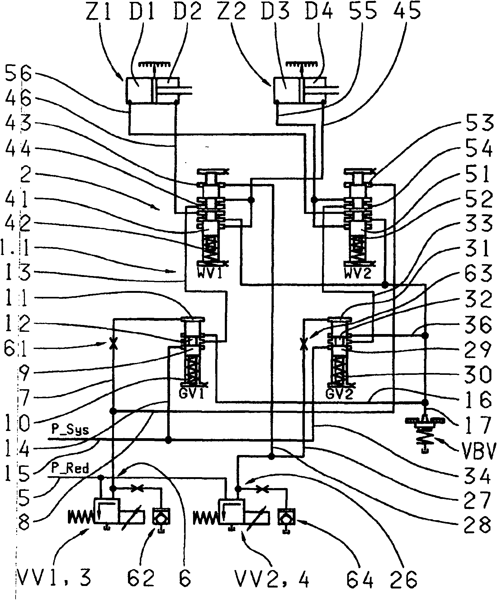
[0036] Corresponding to the embodiment of the control device described in DE 103 47 203 A1 with reference to FIG. 43 there, the known hydraulic control device 1.3 of the dual clutch transmission according to Figure 6 It has: four double-acting gear servo cylinders Z1-Z4, which each have two pressure chambers D1-D8 for the assigned gears G1-G7 and R to engage and remove gears; two The pressure-controlled gear adjustment valves GV1, GV2 are used to adjust the working pressure in two of the pressure chambers D1-D8; one has a pressure-controlled sub-transmission selector valve TWV and two pressure-controlled cylinder selector valves ZWV1, ZWV2 The multi-way mechanism 202, the two cylinder selection valves ZWV1, ZWV2 are used to selectively distribute the two gear adjustment valves GV1, GV2 to two of the eight pressure chambers D1-D8; The pre-control valves VV1 and VV2 of the valves 203 and 204 are used to regulate the two gear adjustment valves GV1 and GV2; Select valves TWV, ZW...


PUM


Abstract

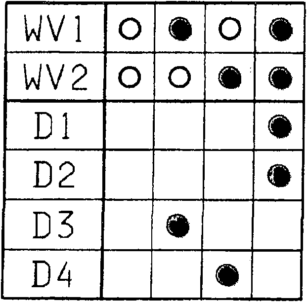
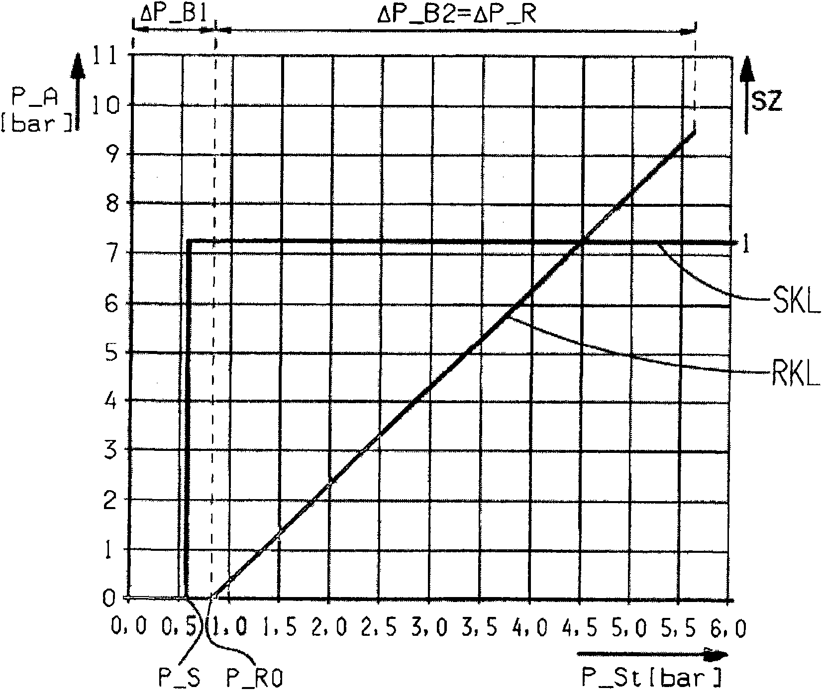
The invention relates to a hydraulic control apparatus of an automated multi-step change-speed gearbox, having a plurality of gear actuating cylinders (Z1 - Z4) for engaging and disengaging the gears of the multi-step change-speed gearbox, having at least two pressure-controlled gear regulating valves (GV1 - GV3) for controlling the operating pressure in in each case one pressure chamber (D1 - D8) of the gear actuating cylinders (Z1 - Z4), and having a multiplex arrangement (2, 102) of a plurality of singly switchable pressure-controlled selection valves (WV1 - WV3) for assigning the gear regulating valves (GV1 - GV3) to in each case one pressure chamber (D1 - D8) of the gear actuating cylinders (Z1 - Z4). In order to simplify the construction and to make broadening of the functional scope of the control apparatus (1.1, 1.2) possible, there is provision for at least one common pilot control valve (W1 - W3) formed as a control valve to be provided for actuating one of the gear regulating valves (GV1 - GV3) and at least one of the selection valves (WV1 - WV3), wherein the pilot control valve (W1 - W3) has a first control pressure range (Delta P_B1) which contains the switching pressure (P_S) of the at least one selection valve (WV1 - WV3) and a second control pressure range (Delta P_B2) which contains the regulating range (Delta P_R) of the gear regulating valve (GV1 - GV3).

Description

technical field [0001] The invention relates to a hydraulic control device of an automatic multi-stage transmission, the control device has: a plurality of gear servo cylinders for engaging and removing gears of the multi-stage transmission; at least two pressure-controlled gear adjustment valves for It is used to control the working pressure in each pressure chamber of the gear servo cylinder; and a multi-way mechanism composed of multiple selector valves that can be controlled by single switch pressure, and these selector valves are used to distribute the gear adjustment valve to the gear servo cylinder. One pressure chamber each. Background technique [0002] For a long time, automatic multi-stage transmissions have been known in different embodiments, not only in the construction type of automatic transmission with a single input shaft and an assigned release clutch, but also in two input shafts assigned by one of the two partial transmissions and A design of a dual-clu...

Claims


Application Information

Patent Timeline
Patent Type & Authority Applications(China)
IPC IPC(8): F16H61/02
CPCF16H61/2807F16H61/0206F16H61/688F16H61/02F16H61/06
Inventor 安东·弗里策尔
Owner ZF FRIEDRICHSHAFEN AG
Learn More