Led lighting circuit and illuminating apparatus using the same
A technology for lighting circuits and LED modules, applied in the field of solutions, can solve problems such as reference current fluctuations and transistor losses, achieve uniform light output and avoid circuit losses.
- Summary
- Abstract
- Description
- Claims
- Application Information
AI Technical Summary
Problems solved by technology
Method used
Image

Examples
Embodiment 1
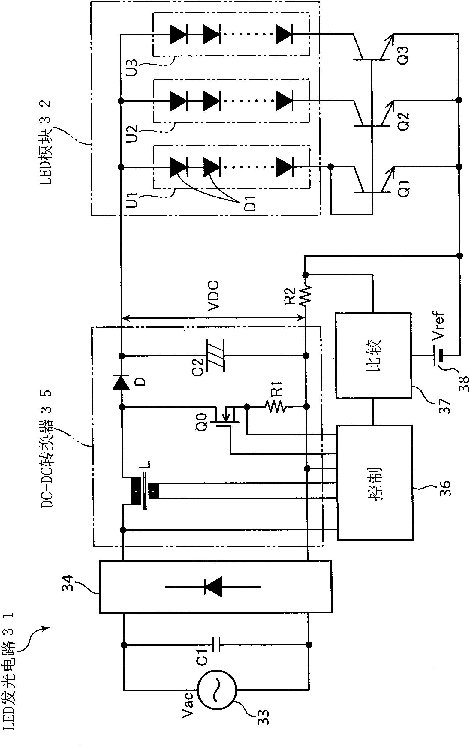
[0048] figure 1 It is a block diagram showing the configuration of the LED lighting circuit 31 according to the first embodiment of the first aspect of the present invention. In this LED lighting circuit 1 , three LED load circuits U1 to U3 in which a plurality of LEDD1 are connected in series are connected in parallel to form an LED module 32 . The number of LED load segments connected in series in each LED load circuit U1-U3 is arbitrary, and a single LED can also be used.
[0049] In each of the LED load circuits U1 to U3, the LED D1 is mounted on a common heat sink and bonded, and a phosphor for wavelength conversion, a lens for light diffusion, and the like are mounted thereon. The LED module 32 and the LED lighting circuit 31 are used as lighting fixtures, the LED load emits blue light or ultraviolet light, and the wavelength of the light emitted by the LED load is converted by the phosphor to emit white light. The number of parallel circuits of the above-mentioned LE...
Embodiment 2
[0065] Figure 5 It is a block diagram showing the configuration of the LED lighting circuit 71 according to the second embodiment of the first aspect of the present invention. In this LED lighting circuit 71, parts similar to and corresponding to those of the above-mentioned LED lighting circuit 31 are denoted by the same reference numerals, and description thereof will be omitted. It is worth noting that, in the LED lighting circuit 71, the LED module 72 is composed of a plurality of LED load circuits U1', U2',..., Un' connected in series in n segments, and each LED load circuit U1', U2', ..., Un' have, a plurality of LEDs D11, D12, ..., D1m; D21, D22, ..., D2m; ...; Dn1, Dn2, ..., Dnm arranged in parallel with each other and connected in series to form a current mirror Control elements of the circuit Q11, Q12, ..., Q1m; Q21, Q22, ..., Q2m; ...; Qn1, Qn2, ..., Qnm.
[0066] Moreover, the LED with the highest conduction voltage Vf ( Figure 5 D11, D2m, ..., Dn2) as a refer...
Embodiment 3
[0118] Figure 16 It is a block diagram showing the structure of the LED lighting circuit 261 according to the third embodiment of the third aspect of the present invention. In this LED lighting circuit 261, the parts similar to and corresponding to those of the above-mentioned LED lighting circuit 231 are denoted by the same reference numerals, and description thereof will be omitted. It should be noted that, in the LED lighting circuit 261, impedance elements A2, A3 are provided in parallel between terminals of the LED load circuits U2, U3 whose control elements Q2, Q3 are not in the diode structure in the LED module 32b. The impedance elements A2, A3 reduce the impedance of the corresponding LED load circuit U2, U3, and clamp the voltage between the terminals to be lower than the voltage between the terminals of the above-mentioned LED load circuit U1, for example Figure 16 The shown may be constituted by a zener diode, or a structure including a resistance element connec...
PUM
 Abstract
Description
Claims
Application Information
 - R&D
- Intellectual Property
- Life Sciences
- Materials
- Tech Scout
- Unparalleled Data Quality
- Higher Quality Content
- 60% Fewer Hallucinations
Browse by: Latest US Patents, China's latest patents, Technical Efficacy Thesaurus, Application Domain, Technology Topic, Popular Technical Reports.
© 2025 PatSnap. All rights reserved.Legal|Privacy policy|Modern Slavery Act Transparency Statement|Sitemap|About US| Contact US: help@patsnap.com