Retrofit digital mammography detector

一种数字射线、检测器的技术,应用在医学成像系统领域,能够解决增加部件包装限制、射线照相图像困难、诊断图像有延迟等问题

Inactive Publication Date: 2009-09-16
CARESTREAM HEALTH INC
View PDF9 Cites 8 Cited by
  • Summary
  • Abstract
  • Description
  • Claims
  • Application Information

AI Technical Summary

Problems solved by technology

Conventional film-based systems include problems with delays in obtaining diagnostic images, the need for chemical or thermal processing, and difficulties in delivering radiographic images outside of point-of-care devices
At the same time, AEC compatibility is an important requirement for compatibility with existing radiology systems, further increasing the constraints of component packaging
Providing the required distance of chest wall access is more of a challenge

Method used


Image

  • Retrofit digital mammography detector
  • Retrofit digital mammography detector
  • Retrofit digital mammography detector

Examples


Embodiment Construction

[0040] The following is a detailed description of the preferred embodiment of the present invention, in which the same reference numerals are used to identify the same elements in the structure of each figure.

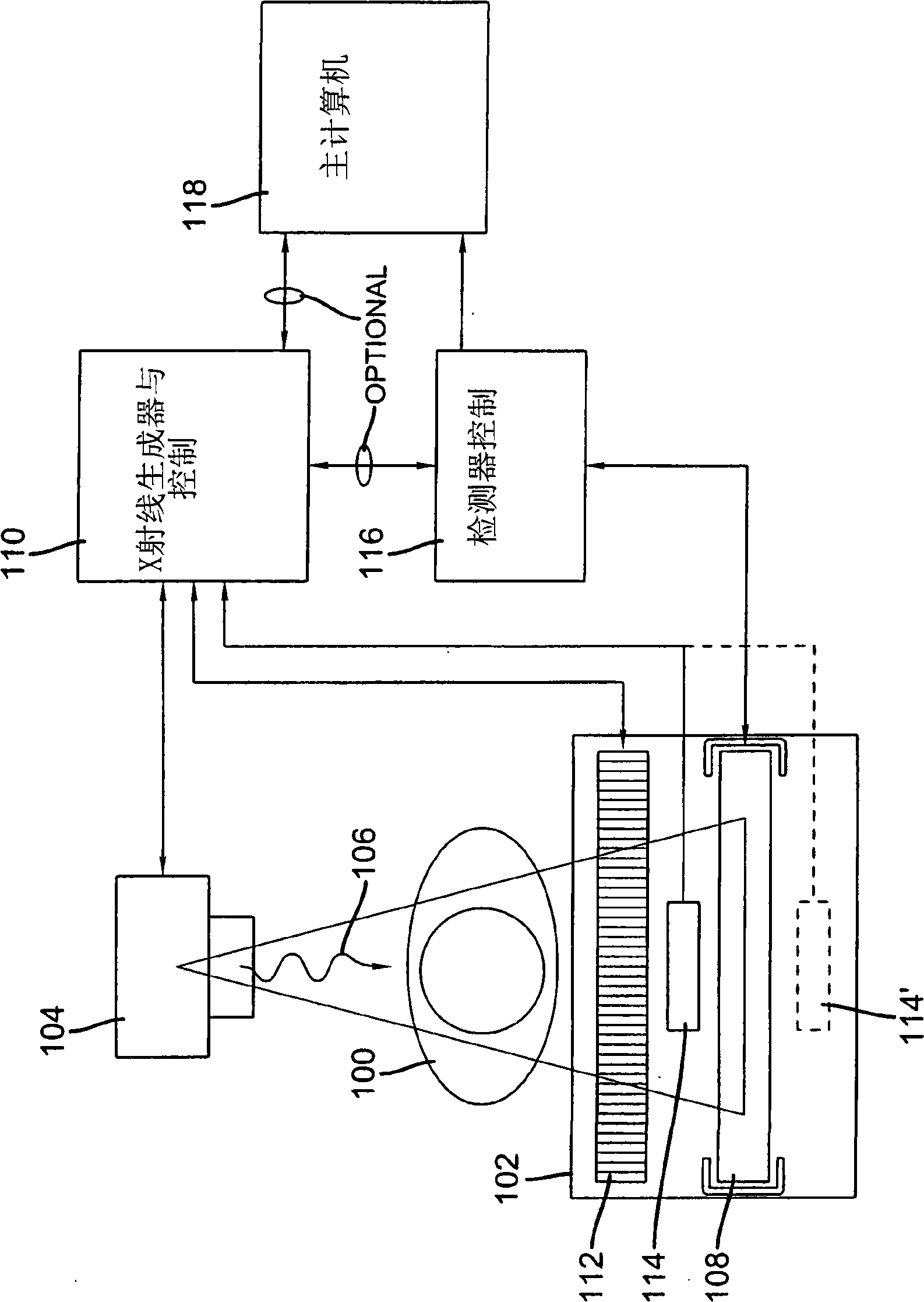
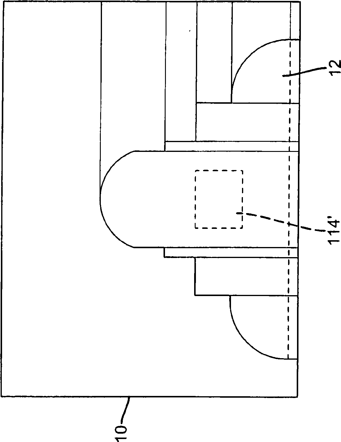
[0041] now refer to figure 1 , which shows a typical X-ray emitting device used in an X-ray examination room. As shown, patient 100 is positioned on support 102 . An x-ray source 104 emits x-rays 106 which pass through a body part of a patient to form a corresponding radiographic image of the human body (anatomy). X-rays 106 are detected by digital detectors built into radiographic cassettes 108 in cradle 102 . The X-ray generation controller 110 activates and controls the X-ray source 104 . The bracket 102 (with a large stand, bucky) can also have an anti-scatter grid 112 built in. An automatic exposure control (AEC) sensor 114 may be placed in the path of the X-rays 106 ahead of the radiographic cassette 108 . Alternatively, an automatic exposure control (AEC) s...


PUM


Abstract

A digital radiography ( 20 ) detector has a first housing ( 18 ) having substantially the form factor of a film cassette and having a chest wall edge (C). The first housing ( 18 ) has an X-ray converter ( 70 ) with a detection array ( 26 ), each detector generating a signal according to an amount of radiation received. Readout electronics ( 74 ) are coupled with switching elements in the detection array for obtaining the signals therefrom. The readout electronics ( 74 ) include elements formed from crystalline silicon and are distributed toward outer edges of the first housing ( 18 ) and awayfrom the chest wall edge (C). X-ray shielding selectively protects the readout electronics ( 74 ) and is located beneath a portion of the detection array. A second housing ( 40 ), electrically connected to the first housing ( 18 ) has a power source for the detector, readout and control electronics for obtaining signals provided from the detection array ( 26 ).

Description

technical field [0001] The present invention relates generally to medical imaging systems employing digital radiography detectors, and more particularly to a digital radiography detector that can be retrofitted to existing film-based chest radiography exposure systems. Background technique [0002] Conventional film-screen radiography has long been used as a medical imaging diagnostic system. X-rays are shone through parts of the patient's body to a cassette containing a scintillator screen. A scintillator screen converts X-rays into light, forming a latent radiographic image on film that lies in direct contact with the screen. The film is then chemically or thermally processed to produce viewable radiographic images for use by health care professionals for diagnosis. Conventional film-based systems include problems with delays in obtaining diagnostic images, the need for chemical or thermal processing, and difficulties in providing radiographic images outside the point-of...

Claims


Application Information

Patent Timeline
Patent Type & Authority Applications(China)
IPC IPC(8): G01T1/24G01T1/29
CPCA61B6/4233G01T1/2928A61B6/502A61B6/563G01T1/244G01T1/24
Inventor T·J·沃奇克J·W·拜恩B·S·加德里奇M·E·夏菲尔K·-L·叶
Owner CARESTREAM HEALTH INC
Why Eureka
Try Eureka