Shielded x-ray detector

a shielded x-ray and detector technology, applied in the direction of material analysis using wave/particle radiation, instruments, radiation control devices, etc., can solve the problems of high cost associated with mechanically mounting and rotating the scintillator, one plane is in focus at any time, and the topology mapping is expensive, difficult and time-consuming

Inactive Publication Date: 2005-02-08
AGILENT TECH INC
View PDF9 Cites 9 Cited by
  • Summary
  • Abstract
  • Description
  • Claims
  • Application Information

AI Technical Summary

Problems solved by technology

One of the drawbacks of such a system is the high cost associated with mechanically mounting and rotating the scintillator.
Another drawback is that only one plane is in focus at any time.
Unfortunately, topology mapping is costly, difficult and time consuming.
One of the drawbacks encountered when converting x-rays to an electrical signal is that not all of the x-rays that impinge on the cesium iodide scintillator are converted to photons.
Some of the x-rays pass through the scintillator and tend to impinge on the CCD array to a degree such that the x-rays degrade the CCD elements over time.
Further, the x-rays tend to create noise in the CCD elements, thereby degrading the quality of the electrical signal supplied by the CCD array.
Unfortunately, existing glass materials that could attenuate the x-rays would be overly thick and would tend to degrade (i.e., become yellow) when exposed to x-rays over an extended period of time.

Method used


Image

  • Shielded x-ray detector
  • Shielded x-ray detector
  • Shielded x-ray detector

Examples


embodiment 700

FIG. 7 is an alternative embodiment 700 of the x-ray detector 300 of FIG. 3A. The x-ray detector 700 includes a direct x-ray conversion element 702. The direct x-ray conversion element 702 converts x-ray energy into an electrical signal. The x-ray detector 700 also includes an array 706 of electrical conductors, an exemplary one of which is illustrated using reference numeral 708. Electrical conductor 708 can be, for example but not limited to, a metallic conductor, or any other structure for conducting an electrical signal from the direct x-ray conversion element 702. The x-ray detector 700 also includes a PCB 720 over which an array 722 of analog-to-digital (A-to-D) converters, an exemplary one of which is illustrated using reference numeral 724, is located.

The x-ray detector 700 includes portions 710 and 712 of a first attenuation material, which is similar to the first attenuation material described above with respect to FIG. 3A. In accordance with this embodiment of the inventi...

embodiment 800

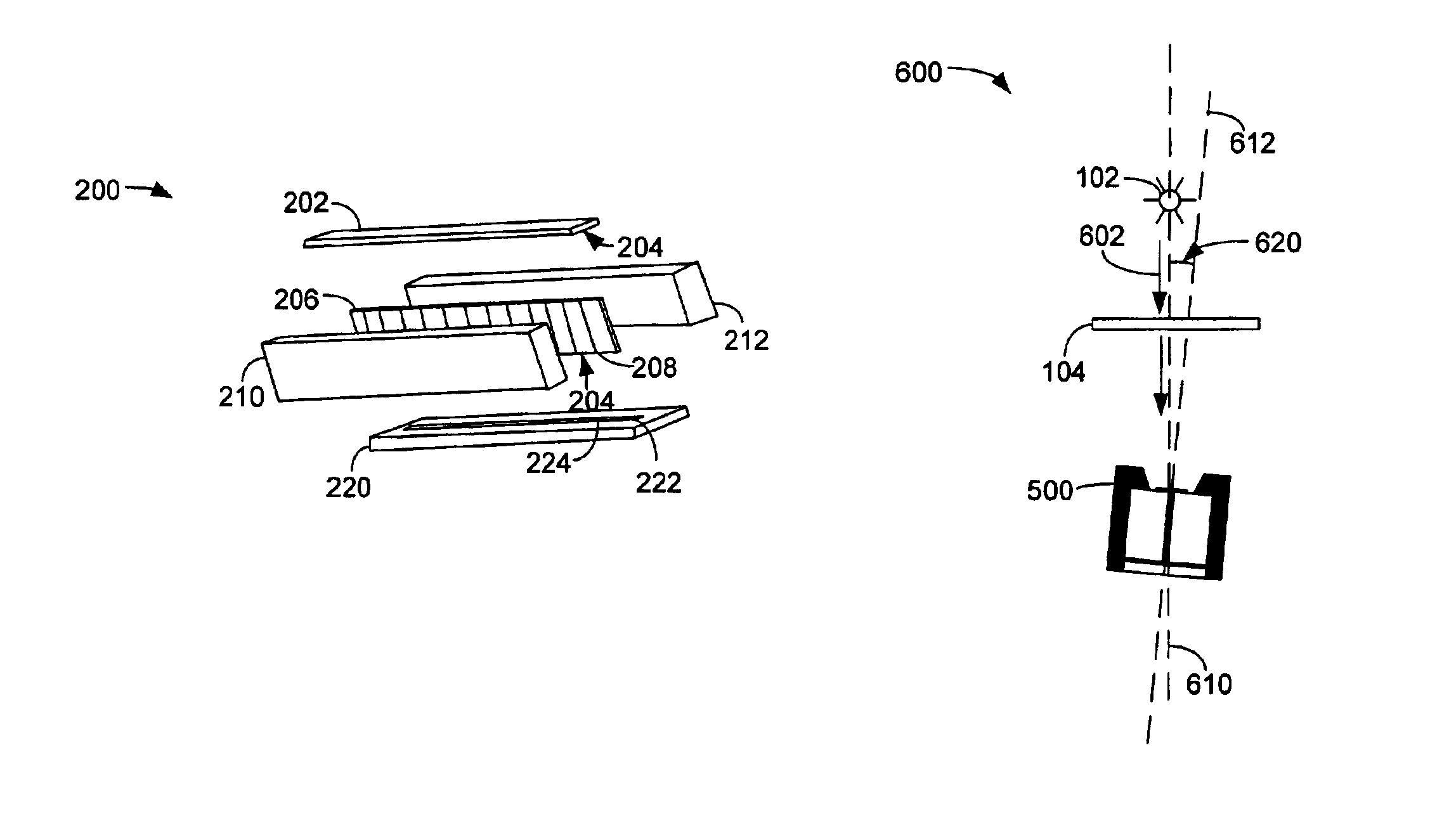
FIG. 8 is an alternative embodiment 800 of the x-ray detector 500 of FIG. 5 The x-ray detector 800 includes a gap 806 instead of the optical fibers described above with respect to FIG. 5. The gap 806 defines one or more discrete optical channels (e.g., an optical waveguide) that transport the visible light indicated using reference numeral 805 from the scintillator 202 to each light sensitive element of the light sensing element 222. Each optical channel may contain, for example, air, an inert gas, or, as will be described with respect to FIG. 9, a liquid.

A reflective coating, such as, for example, gold or aluminum, or a combination thereof, is applied to the surfaces 810 and 815 of the portions 210 and 212 of the first attenuation material that border the gap 806 In this manner, the visible light 805 provided by the scintillator 202 is conducted through the gap 806 by bouncing off the reflective surfaces 810 and 815. However, the x-ray energy that passes through the scintillator 20...

embodiment 900

FIG. 9 is an alternative embodiment 900 of the x-ray detector 800 of FIG. 8. In FIG. 9, the gap 806 is filled with an optically conductive fluid 920, through which the visible light indicated using reference numeral 805 travels. In similar fashion to that described above with respect to FIG. 8, the x-ray energy indicated using reference numerals 502a, 502b and 502c is attenuated as described above.


PUM


Abstract

An x-ray shielded imaging detector is disclosed. In one embodiment, the x-ray shielded imaging detector comprises a scintillator, a photodetector, and an optical connection between the scintillator and the photodetector. The x-ray shielded imaging detector also includes a first high density shielding material adjacent the optical connection. The first high density shielding material absorbs x-ray energy and attenuates it before the x-ray energy reaches the photodetector when the x-ray energy impinges on the x-ray shielded imaging detector at an angle other than perpendicular to a major axis of the scintillator and the photodetector. Other embodiments and related methods of operating an x-ray system are also disclosed.

Description

BACKGROUND OF THE INVENTIONMany non-destructive testing applications use x-ray radiation to locate objects that are within other structures. For example, x-ray detection is used to image dense objects, such as human bones, that are located within the body. Another application of x-ray detection and imaging is in the field of non-destructive electronic device testing. For example, x-ray imaging is used to determine the quality of solder that is used to connect electronic devices and modules to printed circuit boards.X-ray imaging works by passing electromagnetic energy at wavelengths of approximately 0.1 to 100×10−10 meters (m) through the target that is to be imaged. The x-rays are received by a receiver element, known as an x-ray detector, on which a shadow mask that corresponds to the objects within the target is impressed. Dark shadows correspond to dense regions in the target and light shadows correspond to less dense regions in the target.The dark portions of the shadow mask ge...

Claims


Application Information

Patent Timeline
Patent Type & Authority Patents(United States)
IPC IPC(8): G01T1/20G01T1/202G01T1/00G01T1/208
CPCG01T1/202G01T1/2018
Inventor KERSCHNER, RONALD K
Owner AGILENT TECH INC
Why Eureka
Try Eureka