Optical disc drive and method of controlling the same

A technology of optical disc drives and optical discs, which is applied to instruments, information recording on magnetic discs, head configuration/installation, etc., and can solve problems such as difficult to determine the type of optical disc

Inactive Publication Date: 2009-09-23
SAMSUNG ELECTRONICS CO LTD
View PDF0 Cites 0 Cited by
  • Summary
  • Abstract
  • Description
  • Claims
  • Application Information

AI Technical Summary

Problems solved by technology

In contrast, in organic optical discs, since the amplitude of the wobble signal with in-groove polarity is close to that of the wobble signal with on-groove polarity, it is difficult to determine the type of optical disc only by the amplitude of the wobble signal

Method used


Image

  • Optical disc drive and method of controlling the same
  • Optical disc drive and method of controlling the same
  • Optical disc drive and method of controlling the same

Examples


Embodiment Construction

[0038] Reference will now be made in detail to embodiments of the present general inventive concept, examples of which are illustrated in the accompanying drawings, wherein like reference numerals refer to like elements throughout. The embodiments are described below in order to explain the present general inventive concept by referring to the figures.

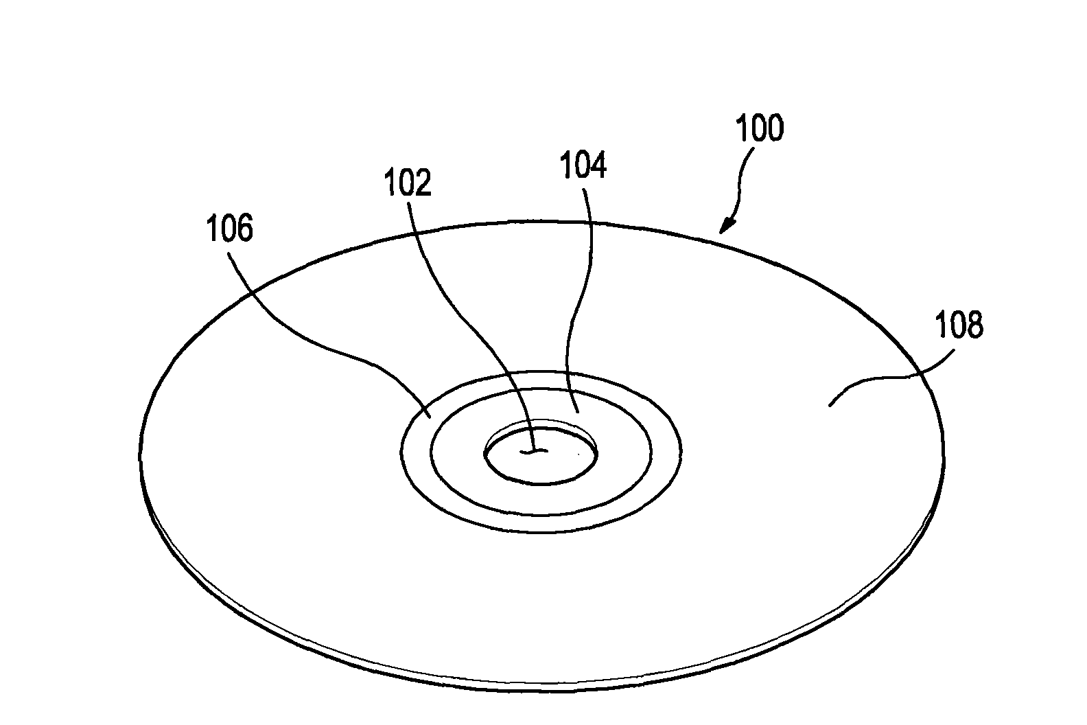
[0039] The following will refer to Figures 1 to 6 Exemplary embodiments of the present general inventive concept are described. figure 1 is an external view showing an optical disc according to an embodiment of the present general inventive concept. Such as figure 1 As shown, a card hole 102 is provided at a central portion of an optical disc 100 having a recording layer for recording information, and one end of a rotation shaft for rotating the optical disc 100 is inserted into the card hole 102 . A clamping portion 104 for fixing the rotating optical disc 100 is provided at a peripheral portion of the clamping hole 102 ....


PUM


Abstract

A method of controlling an optical disc drive in which determining an organic optical disc using a tracking control polarity (in-groove polarity) of the organic optical disc and a reflection amount characteristic (low to high characteristic) after recording and improving the determination speed of the optical disc is possible. The method of controlling an optical disc drive includes detecting a first average value (418) and a second average value (420) of a differential phase detection tracking error (DPD TE) signal of a loaded optical disc, and determining the type of the loaded optical disc by comparison between the first average value and the second average value of the DPD TE signal.

Description

technical field [0001] The present general inventive concept relates to an optical disc drive, and more particularly, to an optical disc drive reproducing an organic optical disc and an inorganic optical disc and a control method thereof. Background technique [0002] Blu-ray Disc (hereinafter referred to as "BD") has been introduced as a next-generation large-capacity recording medium after Compact Disc (CD) and Digital Video Disc (DVD). BD is capable of storing approximately 25GB of data. When a BD is manufactured as dual layers, the BD can store video and audio data of about 50GB. [0003] BDs are divided into BDs in which the surface of the data recording layer is coated with an organic material and BDs in which the surface of the data recording layer is coated with an inorganic material. Since organic BDs and inorganic BDs have opposite tracking control polarities and different light reflection amount characteristics on the surface of the data recording layer, it is n...

Claims


Application Information

Patent Timeline
Patent Type & Authority Applications(China)
IPC IPC(8): G11B19/12
CPCG11B19/12G11B7/09
Inventor 宇藤年纪
Owner SAMSUNG ELECTRONICS CO LTD
Why Eureka
Try Eureka