Variable magnetic flux electric rotary machine

a magnetic flux and electric rotary machine technology, applied in the direction of motor/generator/converter stopper, dynamo-electric converter control, magnetic circuit shape/form/construction, etc., can solve the problems of loss due to excitation current flow, increase in heat generated in the coil, efficiency deterioration, etc., to achieve wide operation speed range, high efficiency, and improved efficiency

Inactive Publication Date: 2010-07-01
HITACHI LTD
View PDF0 Cites 213 Cited by
  • Summary
  • Abstract
  • Description
  • Claims
  • Application Information

AI Technical Summary

Benefits of technology

[0017]According to the present invention, highly efficient operation in a wide operation speed range can be achieved by mechanically varying the effective flux of an electric rotary machine for magnetic fields. For a motor-generator type electric rotary machine, efficiency can be improved by varying the effective flux depending on revolution speed and torque.

Problems solved by technology

IM motors have the following problem: since a magnetic flux is generated by an excitation current from a stator, a loss due to an excitation current flow may occur.
However, magnetic-field weakening control results in efficiency deterioration because it uses a current not contributory to the torque.
Furthermore, a large current should flow in the armature coil with a resulting increase in the heat generated in the coil.
This means that the following problems may occur: a decline in th

Method used


Image

  • Variable magnetic flux electric rotary machine
  • Variable magnetic flux electric rotary machine
  • Variable magnetic flux electric rotary machine

Examples


first embodiment

[0032]The first embodiment is described below referring to FIG. 1 and FIG. 2A to FIG. 2C.

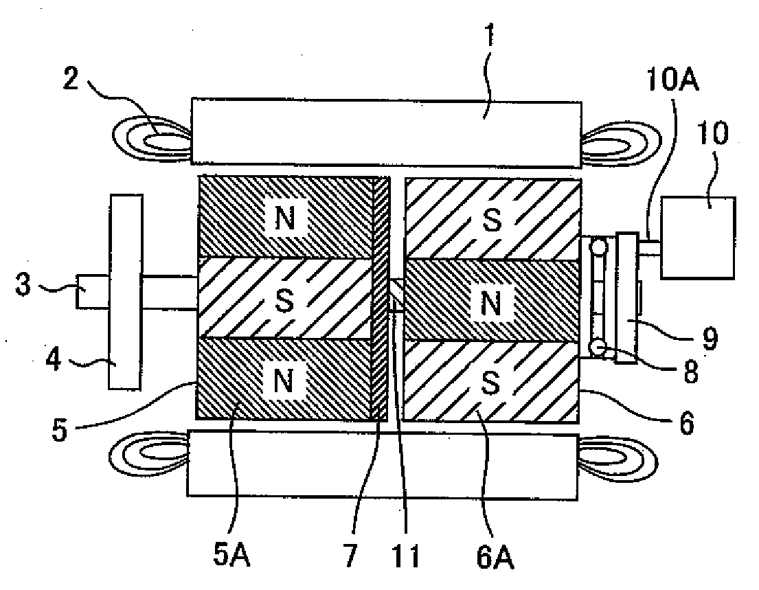
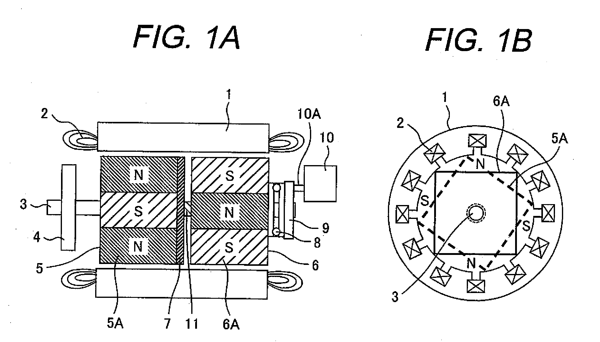
[0033]FIG. 1 shows the structure of an electric rotary machine according to the first embodiment. As shown in FIG. 1, a plurality of open-ended slots (also called grooves) are axially continuously formed in the inner surface of a cylindrical stator core 1 in the rotation direction, with an armature winding 2 (also called a stator winding or primary winding) fitted in each of the slots. The outer side of the stator core 1 is fastened to a housing (not shown) by shrink fitting or press fitting and an end thereof in the axial direction is covered by a bracket 4.

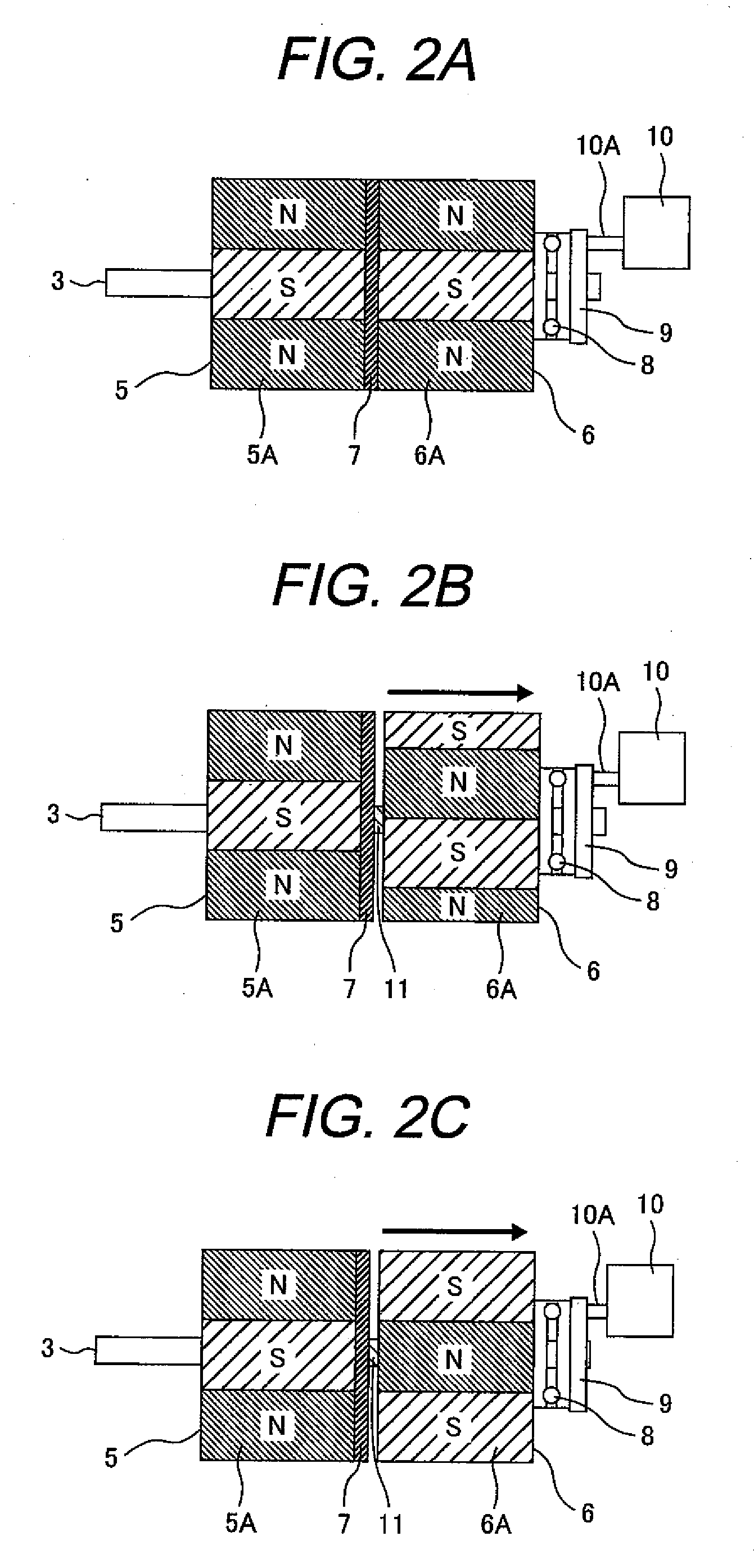
[0034]A rotor is rotatably disposed inside the stator core 1 with a gap from it. The rotor is axially divided into two half rotors which are a first rotor 5 fixed on a shaft 3 and a second rotor 6 which can move axially along the shaft while rotating on a spline 11 provided in the shaft 3. The second rotor 6 provides a spline hole engaged wi...

second embodiment

[0048]The second embodiment is described below referring to FIG. 3A to FIG. 3C. In the description below, the same components as used in the first embodiment are designated by the same reference numerals and their description is omitted and only the components different from those in the first embodiment are described.

[0049]This embodiment concerns an electric rotary machine which has a third rotor 12 between the first rotor 5 and second rotor 6, as illustrated in FIGS. 3A to 3C. In this electric rotary machine, the second rotor 6 and third rotor 12 are activated depending on torque and revolution speed, as shown in FIG. 3A to 3C. More specifically, in this embodiment, there are three stages in which the second rotor 6 and third rotor 12 move axially on the spline 11 as shown in FIG. 3A to FIG. 3C.

[0050]In the stage of FIG. 3A, in which the effective flux should be maximized, the first rotor 5, third rotor 12 and second rotor 6 are brought closer and united and the permanent magnets...

third embodiment

[0062]The third embodiment concerns an improvement in the mechanism for rotation of the second and third rotors relative to the first rotor in the second embodiment. In the description below, the same components as used in the foregoing embodiments are designated by the same reference numerals and their description is omitted and only the components different from those in the foregoing embodiments are described.

[0063]As shown in FIG. 7, the third embodiment uses a flux varying mechanism which includes an interlock means 19 and grooves 20 both located in the third rotor 12 to activate the second rotor and third rotor according to the second embodiment. This mechanism is so designed that by applying a force to one movable wedge 21 laterally, an interlock holder 23 with springs 22 moves the other movable wedge similarly.

[0064]How the second rotor 6 and third rotor 13 are activated is described below referring to FIGS. 8A to 8F. As shown in FIGS. 8A to 8C, projections 24 of the second ...


PUM


Abstract

An electric rotary machine is disclosed which can adjust relative angles of sub-rotors continuously and regardless of torque direction without generating an attractive force between the field magnets of the sub-rotors. The electric rotary machine includes: a stator having a winding; a dual rotor which is rotatably disposed with a gap from the stator and divided axially along a shaft into a first rotor and a second rotor each having field magnets with different polarities arranged alternately in a rotation direction; a mechanism for varying the axial position of the second rotor relative to the first rotor continuously; and a non-magnetic member located between the first rotor and the second rotor.

Description

CLAIM OF PRIORITY[0001]The present application claims priority from Japanese patent application serial No. 2008-331833 filed on Dec. 26, 2008, the content of which is hereby incorporated by reference into this applicationBACKGROUND OF THE INVENTION[0002]1. Field of the Invention[0003]The present invention relates to electric rotary machines which vary the amount of effective flux mechanically depending on torque and revolution speed, and electrical products, vehicles, mobile devices, wind power generation systems, and transport vehicles using the same.[0004]2. Description of the Related Art[0005]The use of permanent magnet synchronous motors (PM motors) which are excellent in efficiency and can be compact and less noisy has been spreading as an alternative to conventional induction motors (IM motors). For example, PM motors are becoming popular as drive motors for household electric appliances, rail cars, and electric vehicles. IM motors have the following problem: since a magnetic ...

Claims


Application Information

Patent Timeline
IPC IPC(8): H02K23/44H02P7/298B60L50/16H02K16/02H02K21/14H02P9/00H02P9/04
CPCH02K21/029B60L2200/26Y02T10/641Y02T10/64
Inventor SHU, KOHINMIYAZAKI, TAIZOKIM, HOUNG JOONGOKABE, SATORU
Owner HITACHI LTD
Why Eureka
Try Eureka