Display Device with Touch Sensor, and Drive Method for the Device

a display device and touch sensor technology, applied in the direction of instruments, computing, electric digital data processing, etc., can solve the problems of degrading the accuracy of position detection of the touch sensor, and achieve the effect of improving the sn ratio, improving the accuracy of position detection, and simplifying the circuit structur

Inactive Publication Date: 2007-11-15
SHARP KK
View PDF5 Cites 207 Cited by
  • Summary
  • Abstract
  • Description
  • Claims
  • Application Information

AI Technical Summary

Benefits of technology

[0063] According to the present invention, noises that occur in currents flowing from terminals of a conductive film for position detection, due to a common voltage which is supplied to a counter electrode of a display panel and which undergoes periodic polarity inversions, are eliminated by using a strobe signal. As a result, the SN ratio is improved, and the accuracy of position detection is improved. Moreover, by generating the strobe signal based on a horizontal synchronizing signal which is supplied to the display panel, the circuit structure can be simplified.
[0064...

Problems solved by technology

In this case, there is a problem in that the touch sensor receives noise from th...

Method used


Image

  • Display Device with Touch Sensor, and Drive Method for the Device
  • Display Device with Touch Sensor, and Drive Method for the Device
  • Display Device with Touch Sensor, and Drive Method for the Device

Examples


Embodiment Construction

[0118] Hereinafter, with reference to the drawings, an embodiment of the touch-sensored display device according to the present invention will be described.

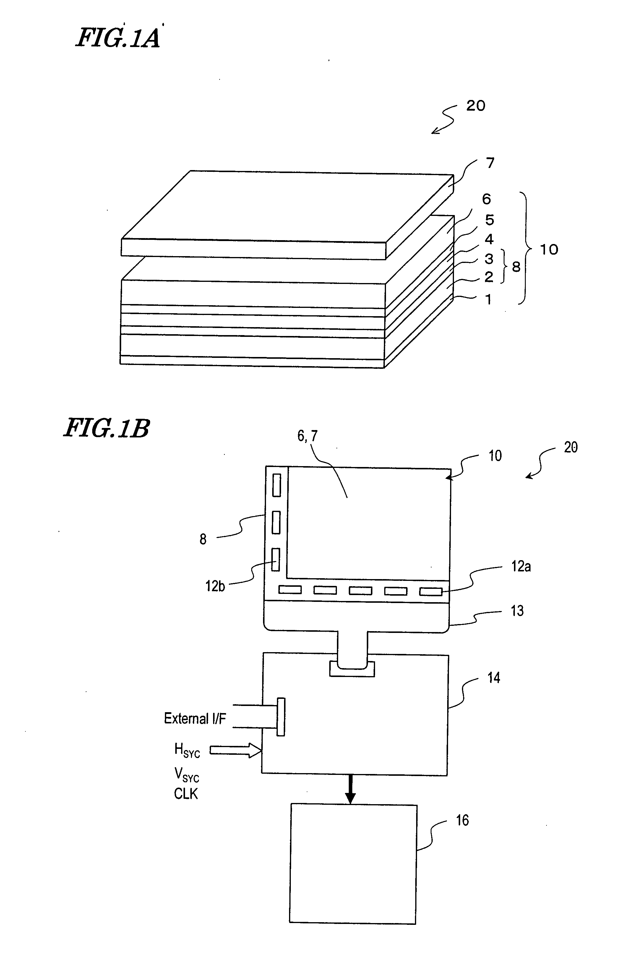
[0119]FIG. 1A and FIG. 1B schematically show the construction of a touch-sensored display device 20 according to one embodiment of the present invention.

[0120] The touch-sensored display device 20 includes a display panel 10 of an active matrix-type (e.g., TFT-type), a transparent conductive film 7 for position detection, a driving circuit 14 for supplying various signals to the display panel 10, and touch panel circuitry 16. Via a FPC (flexible printed circuit) 13, the driving circuit 14 is connected to source drivers 12a and gate drivers 12b which are mounted or formed in a monolithic manner on an active matrix substrate 8 of the display panel 10. Via an external interface (I / F), predetermined signals such as a video displaying signal are supplied, and a horizontal synchronizing signal HSYC, a vertical synchronizing signal VS...


PUM


Abstract

A touch-sensored display device 20 according to the present invention includes: a counter substrate 6 disposed on a viewer side of an active matrix substrate 8 via a display medium layer 4, the counter substrate 6 having a counter electrode 5 which opposes pixel electrodes; a display panel driving circuit 14 for supplying to the counter electrode 5 a common voltage which undergoes periodic inversion in polarity; a transparent conductive film 7 for position detection placed so as to oppose the counter electrode 5 via the counter substrate 6; a strobe signal generation circuit 32 for generating a strobe signal which is in synchronization with a polarity inversion period of the common voltage, and a noise-cut current signal generation circuit 30 for generating a noise-cut current signal which is obtained by eliminating based on the strobe signal a predetermined portion from a current flowing from a terminal connected to the transparent conductive film 7 for position detection.

Description

TECHNICAL FIELD [0001] The present invention relates to a touch-sensored display device which is capable of detecting a position on a display surface that is contacted with a pen, a finger, or the like, and a driving method thereof. BACKGROUND ART [0002] A touch sensor (“touch panel”) is an input device which performs position detection as to a place where contact with a finger, a pen, or the like is made, and conveys the intent of an operator to an information processing system. Known approaches of position detection are a static capacitive coupling approach, a resistive membrane approach, an infrared approach, an ultrasonic approach, an electromagnetic induction / coupling approach, and so on. [0003] A touch sensor of the static capacitive coupling approach is disclosed in Patent Document 1, for example. A touch sensor of the static capacitive coupling approach is constructed so that terminals for position detection are formed in the four corners of a conductive film for position de...

Claims


Application Information

Patent Timeline
IPC IPC(8): G06F3/041
CPCG06F3/044G06F3/0443
Inventor NISHIMURA, TOMOHIKOMIYAMOTO, SABUROHNAKANO, TOSHIHISAHAMADA, HIROSHIYAMAGUCHI, TAKESHI
Owner SHARP KK
Why Eureka
Try Eureka