Direct current load breaking contact point constitution and switching mechanism therewith

a technology of contact point and current load, which is applied in the direction of circuit-breaking switches, circuit-breaking switches for excess currents, contacts, etc., can solve the problems of cadmium-using relays and switches, abnormal arc continuation, and conduction defects due,

Inactive Publication Date:
View PDF5 Cites 209 Cited by
  • Summary
  • Abstract
  • Description
  • Claims
  • Application Information

AI Technical Summary

Problems solved by technology

When the material is used in movable contacts and stationary contacts, under either direct current loads of direct current resistance load and direct current induction load, problems such as the conduction defect due to consumption of the contact point, locking due to material transfer from one contact point to other contact point, welding between contact points, and abnormal arc continuation have not been experienced over a long period of time.
However, since the AgCdO contact point contains a hazardous material, Cd, in recent years, a movement against the use of the relays and switches that use cadmium is gathering strength.
In such movement, development of switching mechanisms that use contact point materials capable of substituting the AgCdO contact points is urgent.
However, since, in such technology, there are strong and weak load regions of load-breaking switching mechanisms, the above contact point materials cannot necessarily substitute for the AgCdO contact points in both direct current loads of direct current resistance load and direct current induction load.
For details, when the above contact point materials each are independently used as the contact point material common to the movable contact point and stationary contact point, under the direct current induction load, problems such as ① conduction defect due to consumption of the contact point, ② locking due to material transfer from one contact point to other contact point, ③ welding between the contact points, and ④ abnormal arc continuation are caused.
Furthermore, under the direct current resistance load, the problems such as above ② through ④ are caused.
Thus, it is very difficult to replace, by independently using the above cadmium-free contact point materials each as the common contact point material, the AgCdO contact point under both load conditions.
(1) Since the AgZnO system contact point is low in the consumption-resistance, there is danger of insulation deterioration.
(2) Since the AgZnO system contact point is low in the consumption-resistance, the number of lifetime is short.
(3) Since the AgZnO system contact point is very high in the hardness, it is difficult to process into a small contact point.
The AgSnO2InO3 contact point is much in the transfer of the contact point when the direct current induction load is made and broken and frequently causes a problem in that the abnormal arc continuation results.
However, there is a problem in that the large revising takes a very long period of time and needs much expense.
Furthermore, although different cadmium-free materials are tried to use separately as the movable contact point material and the stationary contact point material, it is also difficult to always replace the AgCdO contact point in both of the direct current resistance load and the direct current induction load.
That is, under the both of the above loads, the problems from ① to ④ are not always overcome.
Accordingly, actually the selection of the contact point material has to be carried out while confirming the magnitude of the inductivity of the load to be applied, that is, it is remarkably troublesome.
It is considered that when the contact points are separated under the direct current induction load, since a relatively large energy stored in the load (arc discharge energy) is discharged at once, the contact point material causes not only the transfer described later in ② but also the sticking to the surroundings of the contact point, resulting in consuming one contact point (negative electrode side) and causing the conduction defect.

Method used


Image

  • Direct current load breaking contact point constitution and switching mechanism therewith
  • Direct current load breaking contact point constitution and switching mechanism therewith

Examples


embodiments 1 to 22

[0037](Embodiments 1 to 22)

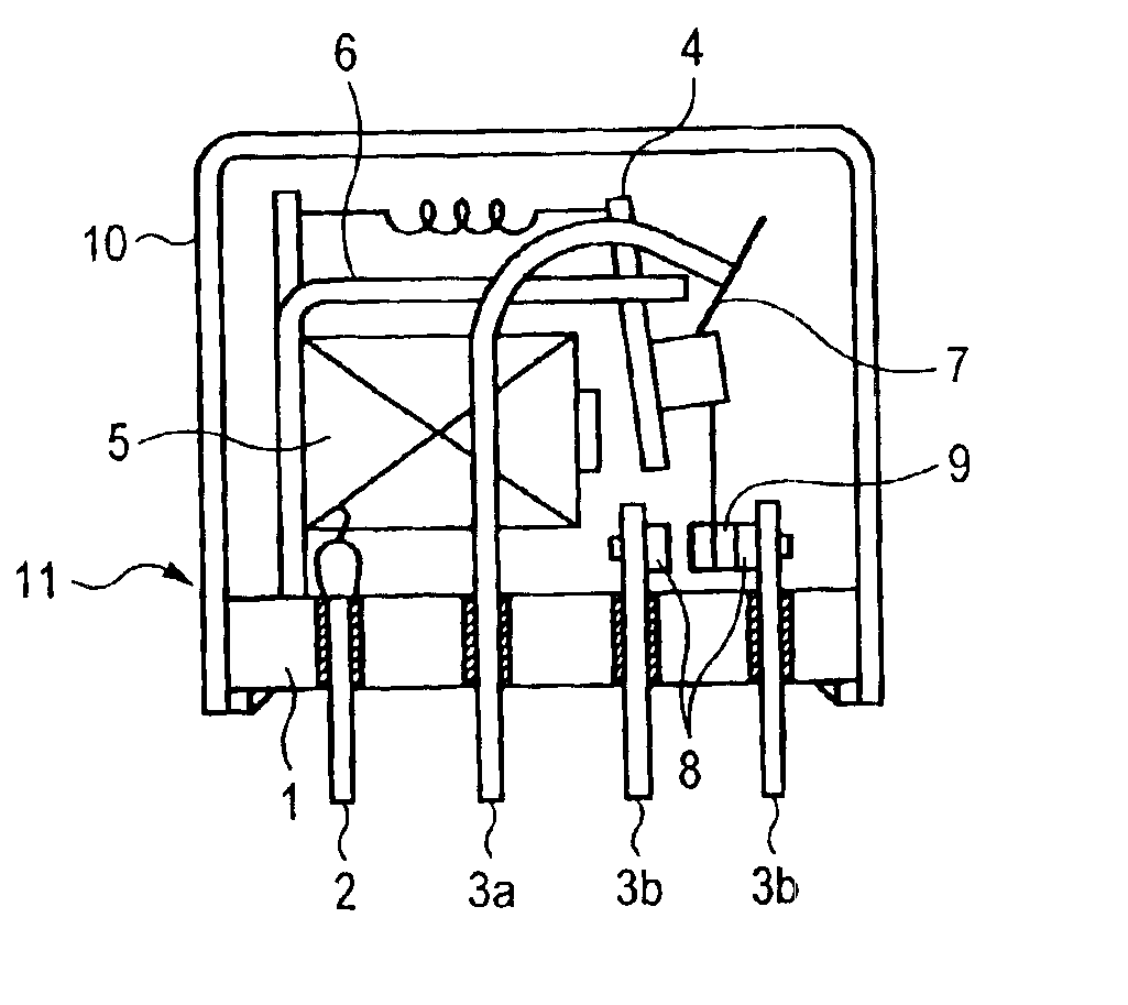
[0038]Rivet contact points (movable contact point, stationary contact point) made of contact point materials described in the table are riveted to a movable contactor and a stationary contactor, respectively, and by assembling these components into a relay, a relay having the constitution shown in FIG. 1 is obtained. In the table, the contact point materials do not contain other metals and metal oxides than the metals and metal oxides described in the table.

[0039]The obtained relay is connected so that the polarity on the movable side may be the predetermined polarity, and is evaluated under the load conditions ① and ② later described. For details, 300,000 times of making and breaking are repeated of each of the relays, and for the direct current resistance load of ① ones that do not exhibit the locking due to the material transfer from one contact point to the other contact point, the welding between the contact points and the abnormal arc continuation ar...


PUM

PropertyMeasurementUnit
timeaaaaaaaaaa
timeaaaaaaaaaa
vapor pressureaaaaaaaaaa

Abstract

The invention intends to provide a direct current load breaking contact point constitution that can make and break an electrical circuit under both direct current loads of direct current resistance load and direct current inductance load over a long period of time without causing problems such as ① the conduction defect due to the consumption of the contact point, ② the locking due to material transfer from one contact point to the other contact point, ③ the welding between the contact points, and ④ the abnormal arc continuation, and a direct current load breaking switching mechanism such as a relay, a switch and so on that has the contact point constitution. The direct current load breaking contact point constitution according to the invention comprises a movable contact point and a stationary contact point that face each other; wherein the movable contact point is made of AgSnO2In2O3 alloy that contains at least Ag, 8 to 15% by weight in total of metal oxides including SnO2 and In2O3, 6 to 10% by weight of SnO2 and 1 to 5% by weight of In2O3; the stationary contact point is made of AgZnO alloy that contains at least Ag and 7 to 11% by weight of ZnO; and polarity of a movable side is (+) and that of a stationary side is (−).

Description

BACKGROUND OF THE INVENTION[0001]1. Field of the Invention[0002]The invention relates to a contact point constitution that makes and breaks a direct current load and a switching mechanism such as a relay and a switching mechanism having the contact point constitution.[0003]2. Description of the Related Art[0004]As a contact point material for a relay or a switching mechanism that makes and breaks an electric circuit, from viewpoint of performance and price, AgCdO alloy has been generally used. When the material is used in movable contacts and stationary contacts, under either direct current loads of direct current resistance load and direct current induction load, problems such as the conduction defect due to consumption of the contact point, locking due to material transfer from one contact point to other contact point, welding between contact points, and abnormal arc continuation have not been experienced over a long period of time. However, since the AgCdO contact point contains ...

Claims


Application Information

Patent Timeline
Patent Type & Authority Patents(United States)
IPC IPC(8): C22C32/00H01H1/02H01H1/04H01H1/0237
CPCC22C32/0021H01H1/04B22F2998/00H01H1/02372H01H1/02376B22F2207/20
Inventor MORI, TETSUYAFUNAKI, KENJITAKAHASHI, YASUSUKEMAENISHI, KOZO
Why Eureka
Try Eureka