
Piezoelectric motor

A technology of piezoelectric motors and motor shafts, applied in electrical components, piezoelectric effect/electrostrictive or magnetostrictive motors, generators/motors, etc., can solve problems affecting motor output, occupation, large space, etc. To achieve the effect of compact structure and increased output

Inactive Publication Date: 2009-09-23
JOHNSON ELECTRIC SHENZHEN
View PDF0 Cites 0 Cited by
  • Summary
  • Abstract
  • Description
  • Claims
  • Application Information

AI Technical Summary

Problems solved by technology

However, this structure still takes up a lot of space
Sometimes the size of the piezoelectric element has to be reduced in order to reduce the footprint, however this will affect the output of the motor

Method used


Image

  • Piezoelectric motor
  • Piezoelectric motor

Examples


Embodiment Construction

[0018] In order to make the technical problems to be solved, technical solutions and beneficial effects of the present invention clearer, the present invention will be further described in detail below in conjunction with the accompanying drawings and embodiments. It should be understood that the specific embodiments described here are only used to explain the present invention, not to limit the present invention.

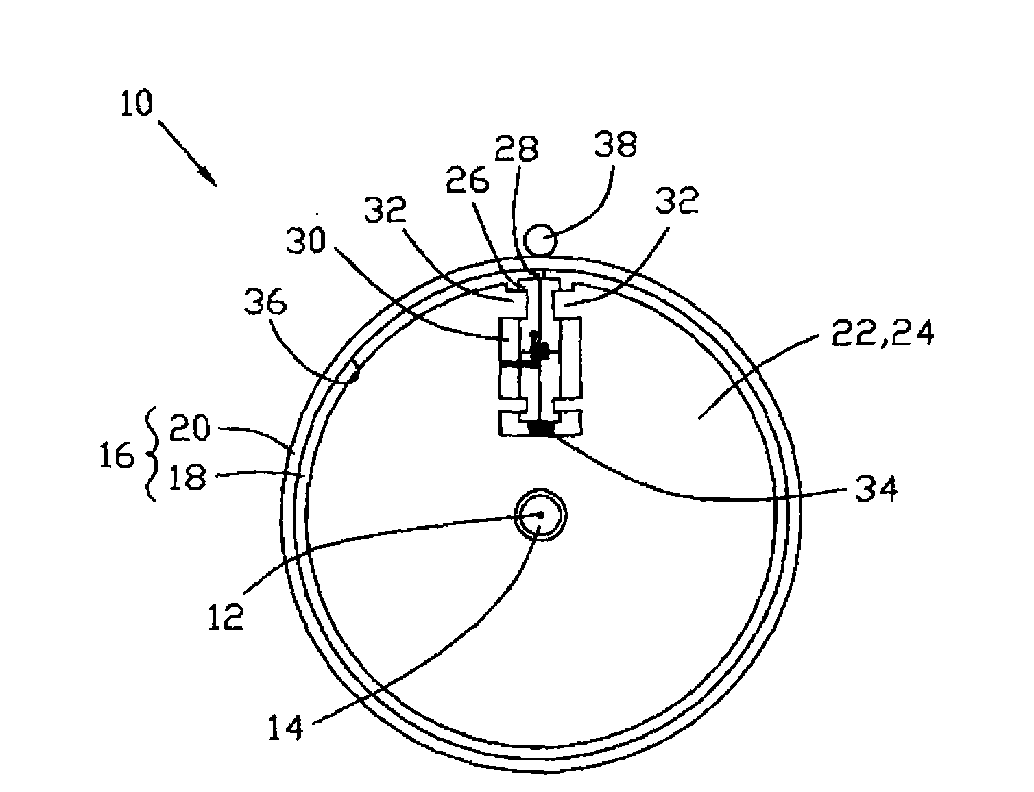
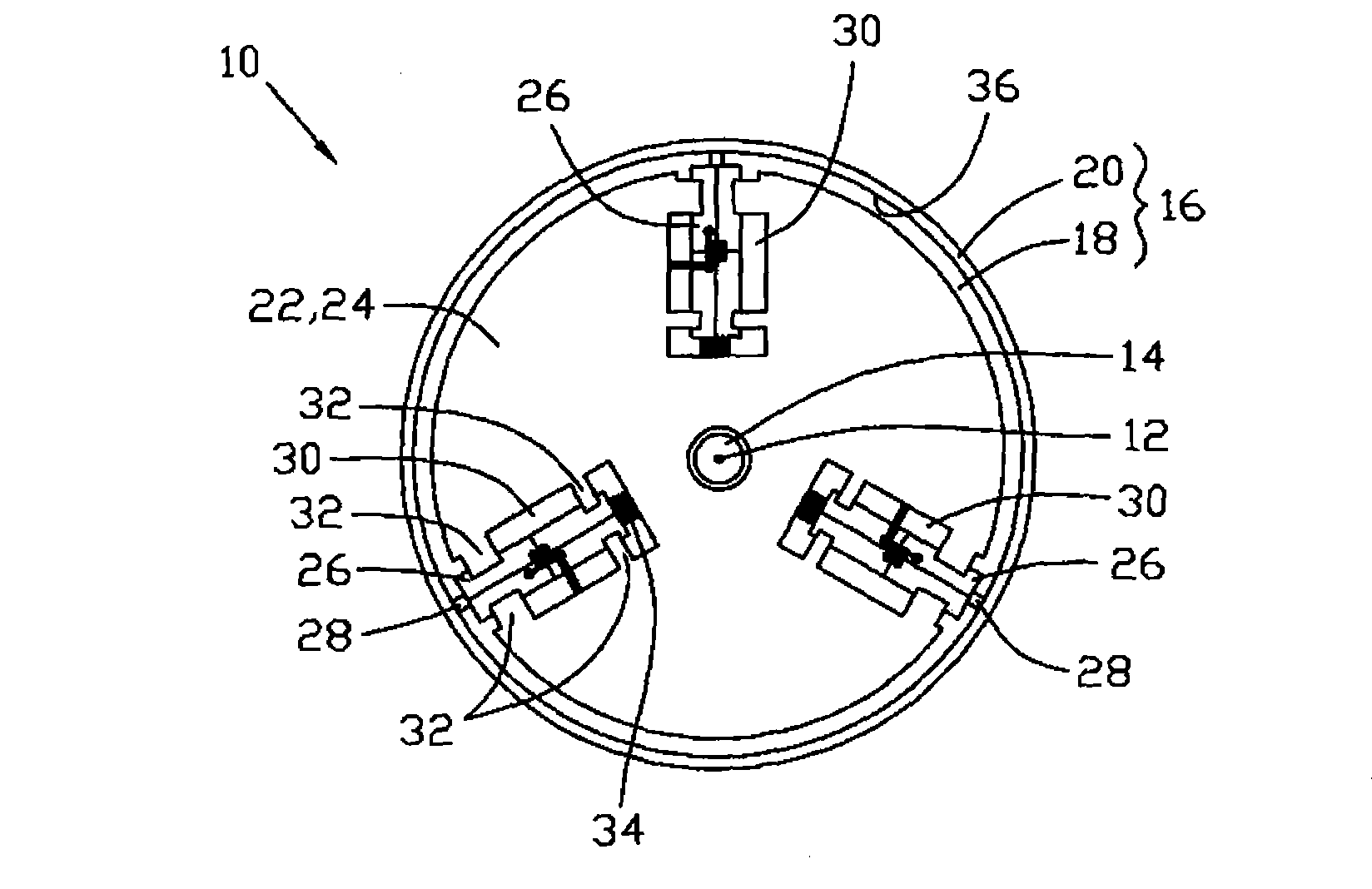
[0019] figure 1 Shown is a side view of a piezoelectric motor 10 perpendicular to the axis 12 provided by the embodiment of the present invention. A motor shaft 14 of piezoelectric motor 10 extends along axis 12 . The piezoelectric motor 10 includes a rotor 16 and a stator 22 . The rotor 16 is fixed on the motor shaft 14 and has a cup-shaped appearance. It includes a body 18 extending radially and a rotating body 20 extending axially from the outer edge of the body 18. A receiving space is formed between the body 18 and the rotating body 20 Between, the stator 2...


PUM


Abstract

The present invention provides a piezoelectric motor, including a motor shaft, having an axial cord; a rotor, capable of rotating around the axial cord, and having a contact face; a stator, including a base, a piezoelectric element with a friction head arranged on the base and an elastic element, arranged between the piezoelectric element and the base for applying a biasing force on the piezoelectric element to maintain the contact between the friction head and the motor shaft. The rotor includes a body and a rotary body extending from the body along an axial direction, the piezoelectric element is arranged in a space enclosed by the body and the rotary body, and the inner surface of the rotary body forms the rotor contact face. In the piezoelectric motor of the invention, the rotor rotates outside the stator, the piezoelectric element is arranged on an inner side of the rotor rotary body, thus the piezoelectric motor has a compact structure, and is capable of increasing an output when using a plurality of piezoelectric elements.

Description

technical field [0001] The invention relates to a piezoelectric motor, in particular to a piezoelectric motor with rotary output. Background technique [0002] Typically, piezo motors can have linear or rotary outputs. In the piezoelectric motor with rotary output in the prior art, the piezoelectric element usually adopts a disc-shaped structure, however, the cost of the disc-shaped piezoelectric element is high and requires a long axial space to accommodate the rotor, piezoelectric element and springs etc. Therefore, the industry began to use block piezoelectric elements. The usual practice is: block piezoelectric elements are arranged outside the rotor body, one end of the piezoelectric element extends with a friction head, and the other end is provided with a spring, and the spring faces the direction of the friction head. Squeeze the piezoelectric element so that the friction head is in frictional contact with the outer surface of the rotating body. However, this stru...

Claims


Application Information

Patent Timeline
IPC IPC(8): H02N2/10
Inventor I·萨埃德
Owner JOHNSON ELECTRIC SHENZHEN
Learn More