Rotor drive of an open-ended spinning apparatus

A driving device, free end technology, applied in the processing of textile materials, bearings, shafts, etc., can solve the problems of spinning rotor wear, uncoordinated adjustment characteristics, and increased implementation costs, and achieve the effect of reducing interference

Inactive Publication Date: 2009-09-23
OERLIKON TEXTILE GMBH & CO KG
View PDF4 Cites 6 Cited by
  • Summary
  • Abstract
  • Description
  • Claims
  • Application Information

AI Technical Summary

Benefits of technology

This patented technology allows for better controllability over how much energy accumulates at certain points along with prevention of damage or malfunctions due to static charges generated while manufacturing processes are being carried out. It achieves this by connecting both the spinner's driving apparatus (rotors) and its supports together into a single structure called a machine frame. When there is no excess potential difference across any two structures, they work like capacitors without causing problems. However, if too many electrons enter their space, then some will get trapped inside instead of moving around freely within the spaces where they were previously located. To solve this problem, the system includes a separate circuit board attached to each side of the motor body. Each plate carries multiple circuits and connects to different terminals on the rotator drive housing through wires. These connections help reduce impedance issues and improve signal quality. Additionally, the use of insulating suspending material reduces unwanted signals and improves overall performance. Overall, this design ensures stable operation even under high levels of stress and provides improved efficiency compared to previous designs.

Problems solved by technology

This patented technical solution describes different ways how to prevent static electricity charged off while spunting fibers or other material through an opening spinning machine (open end) without causing damage. One method involves isolating the spinging rotors' bearings between them and connecting it directly to their grounding parts. Another approach uses conductive elements like springs instead of physically touching them, but also includes applying pressure against these conductive areas to keep the rotation stable over time.

Method used


Image

  • Rotor drive of an open-ended spinning apparatus
  • Rotor drive of an open-ended spinning apparatus
  • Rotor drive of an open-ended spinning apparatus

Examples


Embodiment Construction

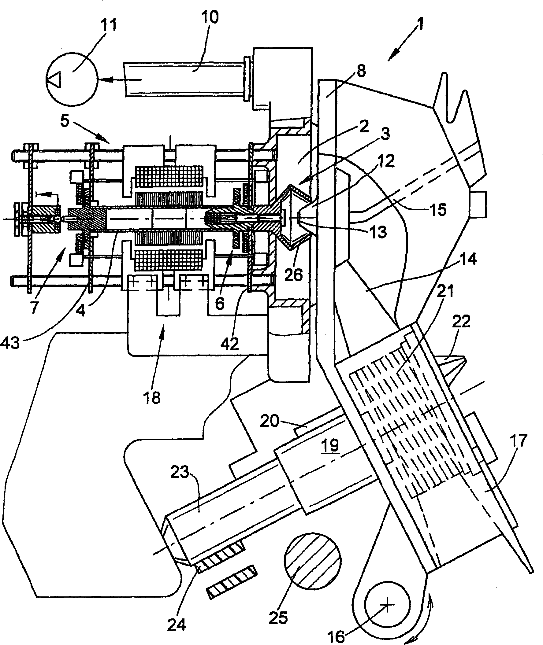
[0023] figure 1 An open-end spinning device 1 is shown, which is known in principle and has been described in detail, for example, in EP 0 972 868 A2.

[0024] Such an open-end spinning device 1 has a rotor housing 2 in which a spinning cup 26 of a spinning rotor 3 rotates at a high rotational speed.

[0025] Usually, the rotor housing 2 , which is itself open on the front, is closed during operation by a pivotally mounted cover element 8 , is connected via corresponding pneumatic lines 10 to a negative pressure source 11 which generates a rotor Necessary spinning negative pressure in housing 2.

[0026] As usual, a channel plate adapter 12 is arranged in the cover element 8 in a replaceable manner, the channel plate adapter 12 having the thread withdrawal mouth 13 and the mouth of the fiber guide channel 14 . The yarn withdrawal nozzle 13 is connected to the yarn withdrawal tube 15 as known. In addition, the opening roller housing 17 is also fixed on the cover element 8 , ...


PUM

PropertyMeasurementUnit
Dielectric strengthaaaaaaaaaa

Abstract

The invention relates to a rotor drive (18) of an open-ended spinning apparatus (1) which has a bearing arrangement (5) for the support of a spinning rotor (3) which rotates at high frequency and is mounted without contact. A rotor shaft (4) of the spinning rotor (3), formed as a runner, is held during the spinning process freely hovering between a front and back bearing (6, 7) of the rotor drive (18). For the conductive discharge of the electrostatic charge occurring during the spinning process,the spinning rotor (3) is distanced from one of the bearings (6, 7) in such a way that when a specified electrostatic charge is reached, a voltage sparkover between the spinning rotor (3) and the bearing (6, 7) occurs, and in such a way that the rotor drive (18) is surrounded by a rotor drive housing (37) which is electrically conductive and grounded and to which the bearing (6, 7) serving for the conductive discharge is conductively connected.

Description


Claims


Application Information

Patent Timeline
Owner OERLIKON TEXTILE GMBH & CO KG
Why Eureka
Try Eureka