Line-type thermal printer

A thermal printer and thermal print head technology, used in printing, transfer materials, power transmission devices, etc., can solve the problems of sufficient separation and inability to line thermal print heads, and achieve the effect of reducing torsional rigidity

Active Publication Date: 2009-09-30
SEIKO EPSON CORP
View PDF1 Cites 11 Cited by
  • Summary
  • Abstract
  • Description
  • Claims
  • Application Information

AI Technical Summary

Problems solved by technology

When there is an automatic centering mechanism, when one end of the head mounting part is pushed by the operating rod, the other end of the head mo

Method used


Image

  • Line-type thermal printer
  • Line-type thermal printer
  • Line-type thermal printer

Examples


Embodiment Construction

[0032] Embodiments of a line thermal printer to which the present invention is applied will be described below with reference to the drawings.

[0033] (the whole frame)

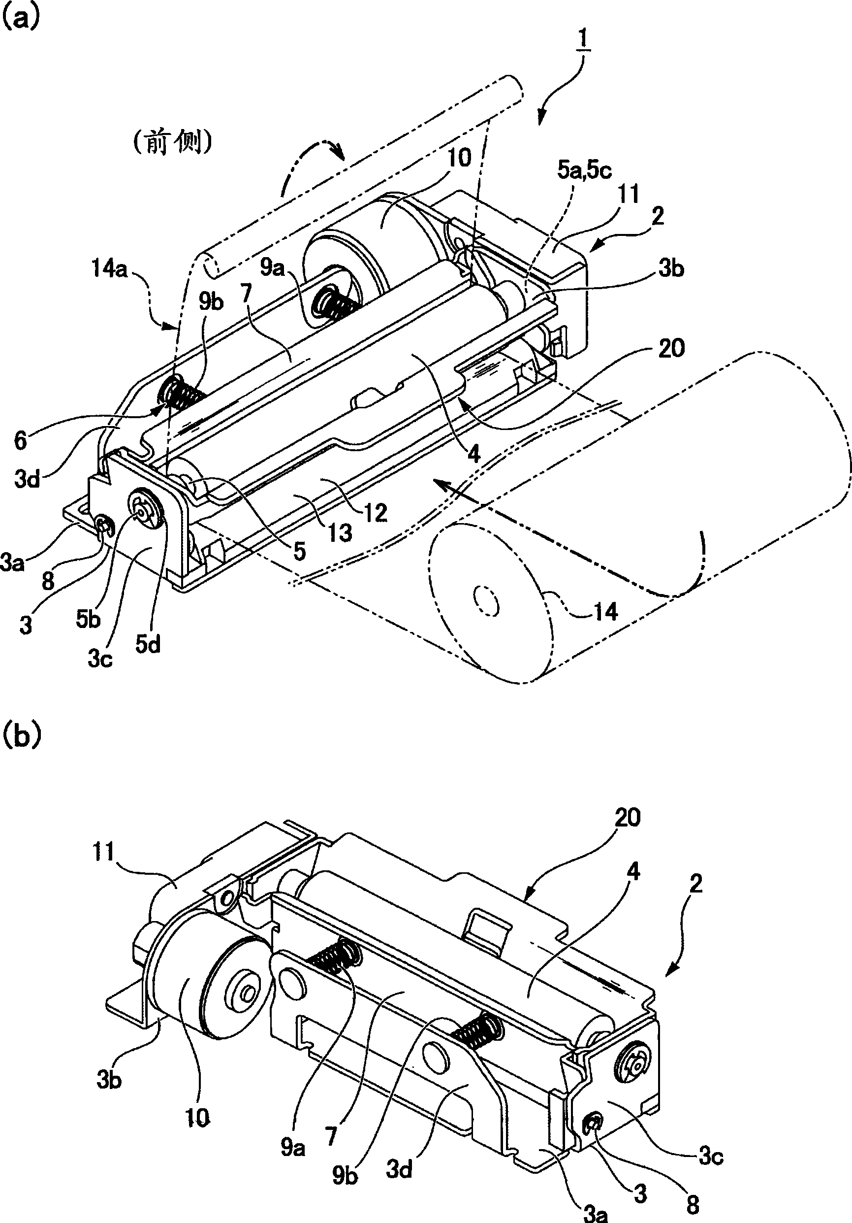
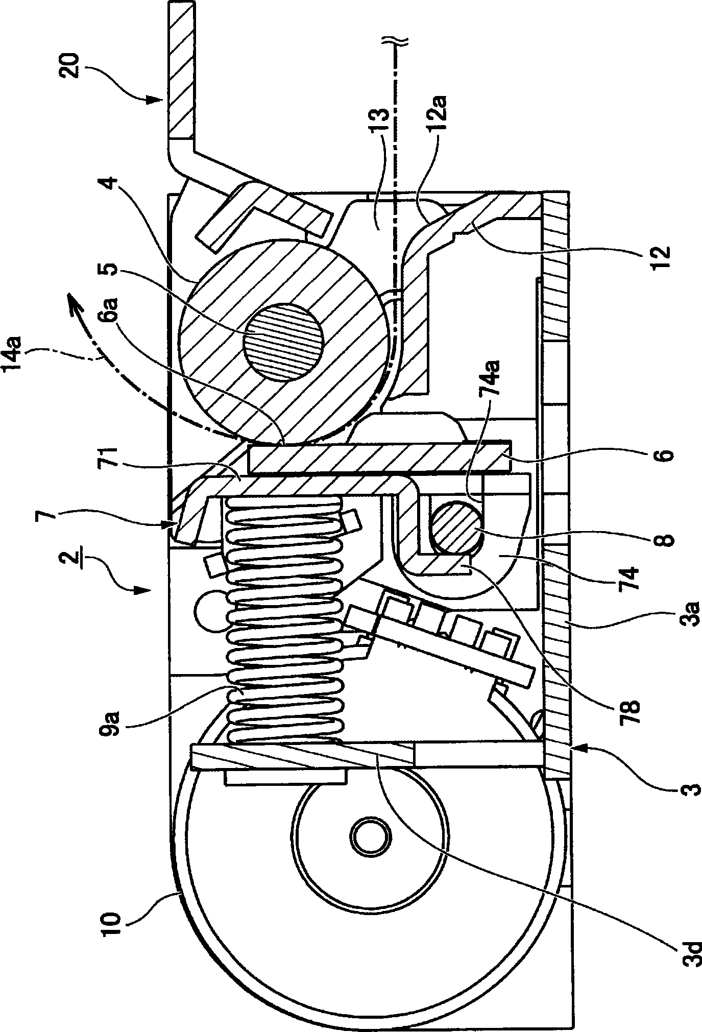
[0034] figure 1 It is a figure which shows the printer mechanism part of the line thermal printer which concerns on embodiment of this invention, (a) is a perspective view seen from the rear side, (b) is a perspective view seen from the front side. and figure 2 It is a schematic sectional view of the printer mechanism.

[0035] The printer mechanism unit 2 of the line thermal printer 1 has a configuration in which each unit is mounted on a printer frame 3 made of a metal plate or the like. The printer frame 3 has a bottom plate portion 3a, left and right side plate portions 3b, 3c, and a rear plate portion 3d. Between the left and right side plate parts 3b, 3c, a platen roller 4 is horizontally erected along the width direction of the printer, and the shaft ends 5a, 5b of the platen shaft 5 protruding l...


PUM


Abstract

The present invention provides a line-type thermal printer which does not generate torsion in a head installation component and can move each part of the line-type thermal printer to open positions which are equally separated from the rider roll. In the line-type thermal printer (1), the head-side joint parts (22c, 23c) which are formed by pushing the operating component side joint parts (22c, 23c) formed at two ends of the operating component (20) to two ends of a head installation plate (7) are used for wholly pushing the head installation plate (7) forwards without torsion. Compared with using the operating component (20) for only operating the single side of the head installation plate (7), the necessary torsion rigidity of the head installation plate (70 can be reduced. The light weight and low cost of the components can be realized. As no torsion is generated in the head installation plate (7), an open state that each component forming the line-type thermal printing head (6) in the width direction of the printer is departed from the rider roll (4) uniformly can be formed.

Description

technical field [0001] The present invention relates to a line thermal printer having an operating member for moving a line thermal printhead to an open position away from a platen. Background technique [0002] In a line thermal printer, recording paper is printed while being conveyed while being pressed against a heat generating surface of a line thermal printhead by a platen roller. When inserting recording paper between the platen roller and the line thermal print head, when removing the recording paper from between them, when cleaning the line thermal print head, etc., it is necessary to keep the line thermal print head from pressing Head opening operation for paper roll exit. [0003] Patent Document 1 discloses a line thermal printer having an operating lever for head opening operation. As described in this patent document, by manually operating the operating lever arranged at one end of the line thermal print head, the head support body on which the line thermal pr...

Claims


Application Information

Patent Timeline
IPC IPC(8): B41J2/32B41J25/304
Inventor 青木崇志
Owner SEIKO EPSON CORP
Why Eureka
Try Eureka