Sliding fork device

A sliding fork and driving device technology, applied in the direction of lifting device, storage device, transportation and packaging, etc., can solve the problems of complex, inability to perform telescopic action smoothly, increase in cost, etc., and achieve cost reduction, reliability improvement, and simplification. effect of structure

Active Publication Date: 2008-09-10
NAKANISHI METAL WORKS CO LTD
View PDF2 Cites 26 Cited by
  • Summary
  • Abstract
  • Description
  • Claims
  • Application Information

AI Technical Summary

Problems solved by technology

[0005] Because in the composition of this existing sliding fork device, the upper movable fork (arm A1, secondary fork 32) closest to it is driven with respect to the fixed fork, and by being linked with the movement of the movable fork, The above-mentioned interlocking mechanism makes the upper movable fork (arm A2, third-stage fork 33) and the uppermost movable fork (arm A3, fourth-stage fork 34) telescopic. The driving force of the driving device makes the structure of sliding the uppermost movable fork more complicated, so the cost increases, and, especially in the case of heavy weight of the object to be transported or a large telescopic stroke, there is a problem that it cannot be carried out smoothly. The telescopic operation of the top-level movable fork (front end fork)

Method used


Image

  • Sliding fork device
  • Sliding fork device
  • Sliding fork device

Examples


Embodiment Construction

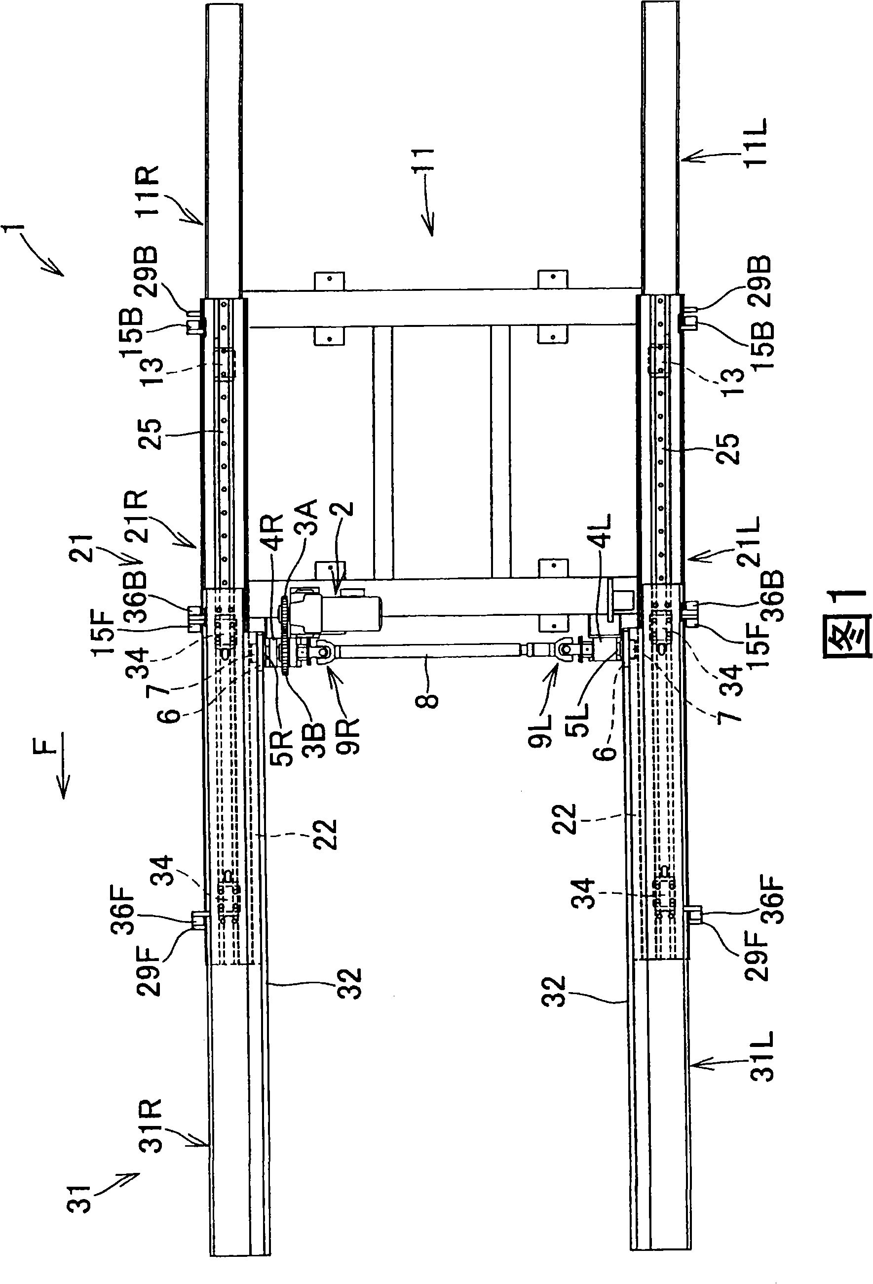
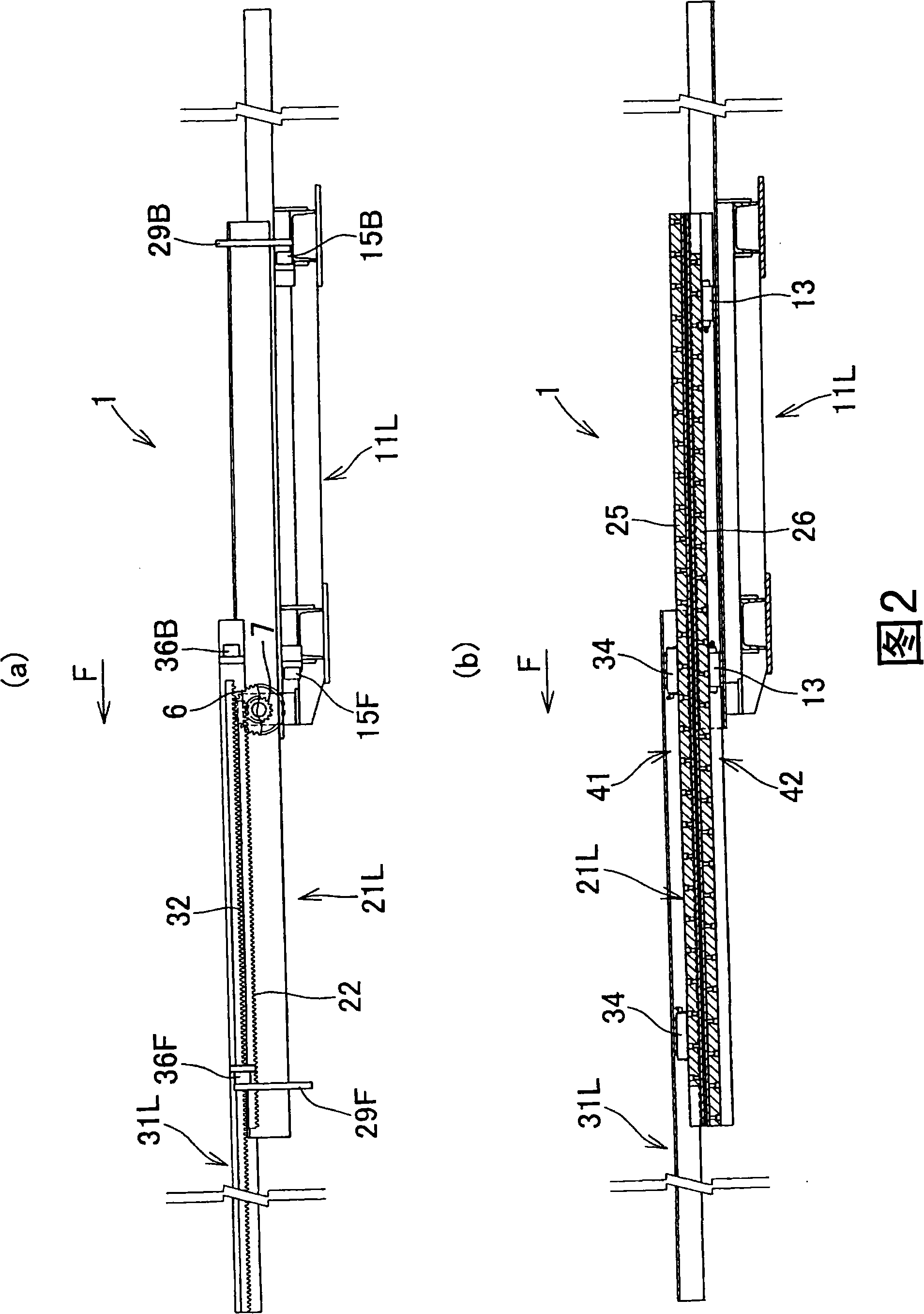
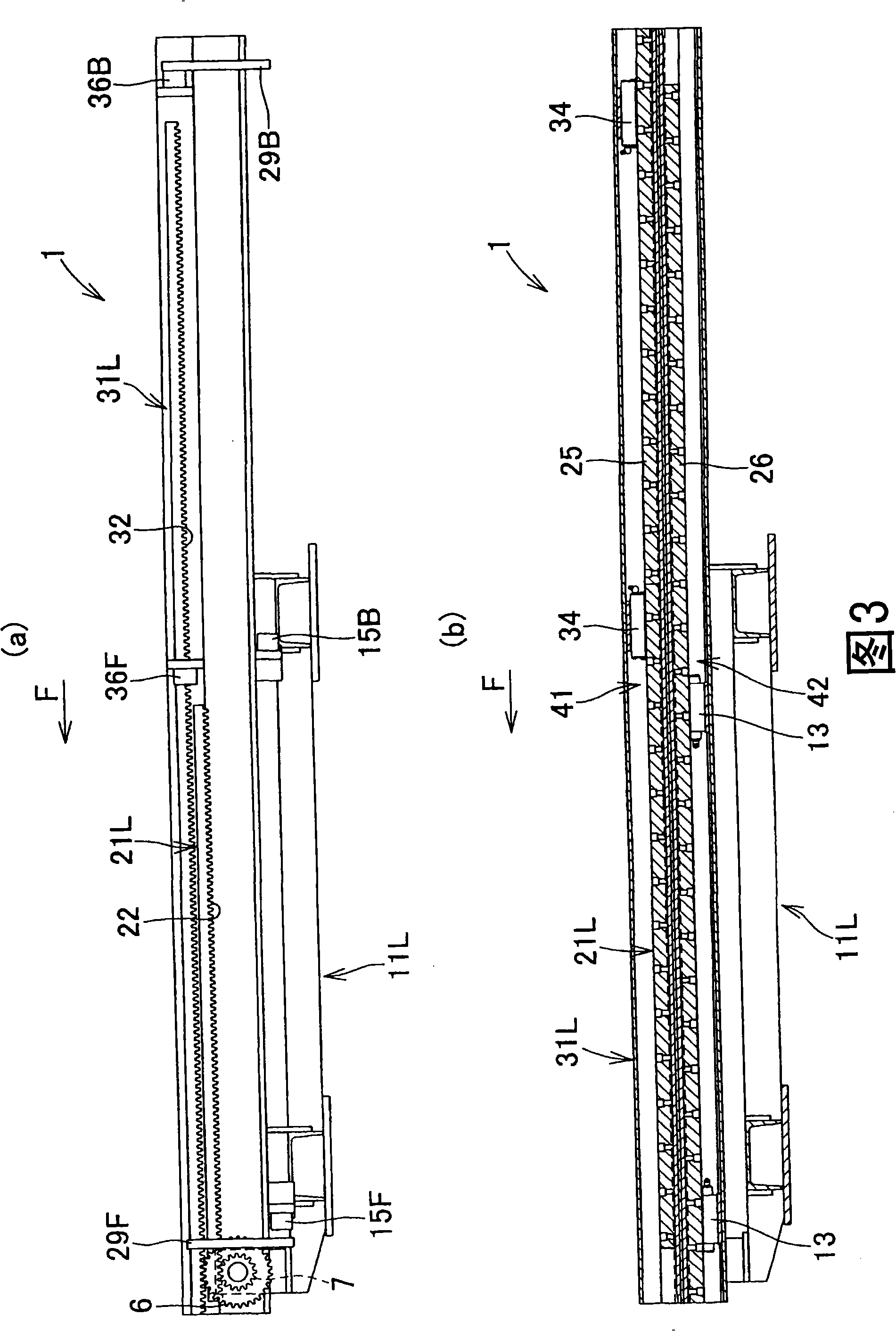
[0019] Embodiments of the present invention will be described in detail below with reference to the drawings, but the present invention is not limited to the embodiments shown in the drawings, and includes all embodiments that satisfy the points described in the claims. In this specification, one direction in which each fork extends (refer to arrow F in the figure) is defined as front, left and right when facing forward are defined as left and right, and a view viewed from the left is defined as a front view.

[0020] Figure 1~ Figure 4 It is an explanatory diagram showing the structure of the sliding fork device according to the embodiment of the present invention, FIG. 1 is a plan view, FIG. 2 is a longitudinal sectional front view of the left fork in a state where the movable fork (middle fork and front end fork) is extended, and FIG. 3 It is a vertical front view of the left fork in the retracted state of the movable fork (middle fork and front fork), Figure 4 It is a rea...


PUM


Abstract

The invention provides a sliding york which can process stretching movement swimmingly and reduce cost even if a carry object has heavy weight or stretching stroke. The sliding york apparatus (1) includes a fixing york (11), a middle york (21) supported to slide along length direction relative to the fixing york (11), and a front york (31) supported to slide along length direction relative to the middle york (21). A drive pinion driven by a rotary drive device (2) mounted on the fixing york (11) engages with a rack (22) mounted on the middle york (21) in the sliding york apparatus (1). All movable yorks (the middle york (21) and the front york (31)) are driven directly by the rotary drive device (2).

Description

technical field [0001] The present invention relates to improvements in slide fork arrangements for cargo transfer devices. Background technique [0002] The sliding fork device used for loading and unloading machinery such as conveyors, forklifts, and cranes to transfer goods has two or more movable forks that slide relative to non-sliding fixed forks, and is composed of a driving mechanism and a linkage mechanism , the drive mechanism is supported as a movable upper stage closest to the fixed fork that can slide in the length direction relative to the fixed fork (fixed frame F in patent document 1, and first-stage fork 31 in patent document 2). Fork (arm A1 in patent document 1, secondary fork 32 in patent document 2) is driven, and the linkage mechanism is to make the upper-level movable fork (in patent document 2) move as the movable fork slides. In 1, the arms A2 and A3, in patent document 2, the third-stage fork 33 and the fourth-stage fork 34) slide in the same direc...

Claims


Application Information

Patent Timeline
Patent Type & Authority Applications(China)
IPC IPC(8): B65G47/00B65G47/74B65G1/04B66F9/12B66F13/00
Inventor 山口晴行
Owner NAKANISHI METAL WORKS CO LTD
Why Eureka
Try Eureka