Hydraulic Driving System

a driving system and hydraulic technology, applied in the direction of fluid couplings, servomotors, couplings, etc., can solve the problem of impaired smooth motion of the boom cylinder

Active Publication Date: 2015-10-15
NIHON KENKI CO LTD
View PDF5 Cites 15 Cited by
  • Summary
  • Abstract
  • Description
  • Claims
  • Application Information

AI Technical Summary

Benefits of technology

[0017]With the fifth feature of the present invention, the control device is configured in such a manner that the hydraulic fluid inlet-flow and outlet-flow control unit for the closed circuit, the hydraulic fluid inlet-flow and outlet-flow control unit for the open circuit, and the first and second opening and closing devices are controlled based on the pressure of the hydraulic fluid in the first flow passage detected by the pressure sensing system. For this reason, driving of the hydraulic fluid inlet-flow and outlet-flow control unit for the closed circuit, the hydraulic fluid inlet-flow and outlet-flow control unit for the open circuit, the first opening and closing device, and the second opening and closing device is more properly controlled by the control device, and the motion of the single rod hydraulic cylinder is further smoothened.

Problems solved by technology

However, if there is a pressure difference between a side of the open circuit and a side of the closed circuit, there is a possibility that smooth motion of the boom cylinder may be impaired because an inlet-flow rate of the hydraulic fluid into the boom cylinder is suddenly changed when the hydraulic fluid on the side of the open circuit and the hydraulic fluid of the side of the closed circuit are merged by the distribution circuit and are fed to the boom cylinder.

Method used


Image

  • Hydraulic Driving System
  • Hydraulic Driving System
  • Hydraulic Driving System

Examples


first embodiment

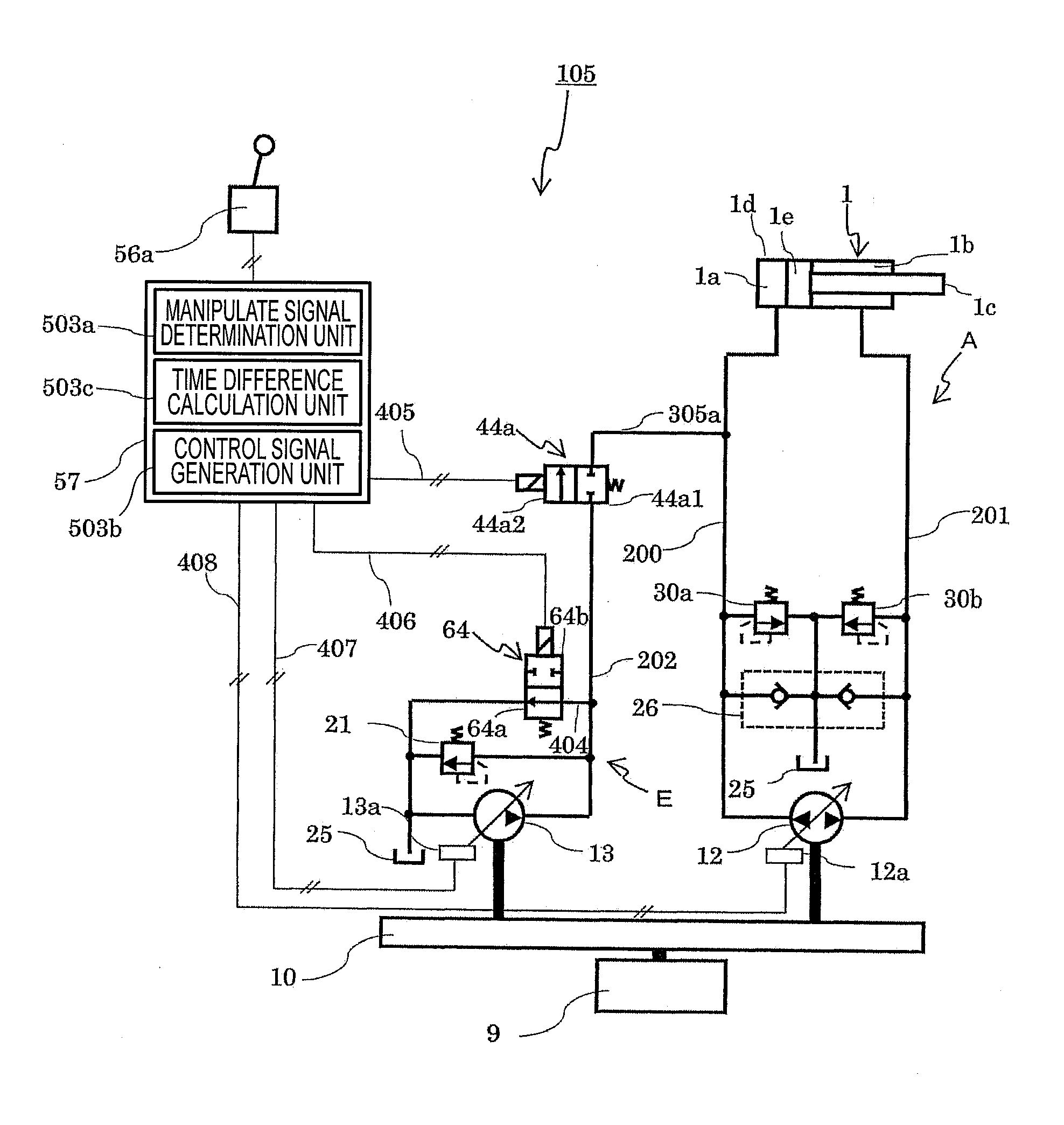
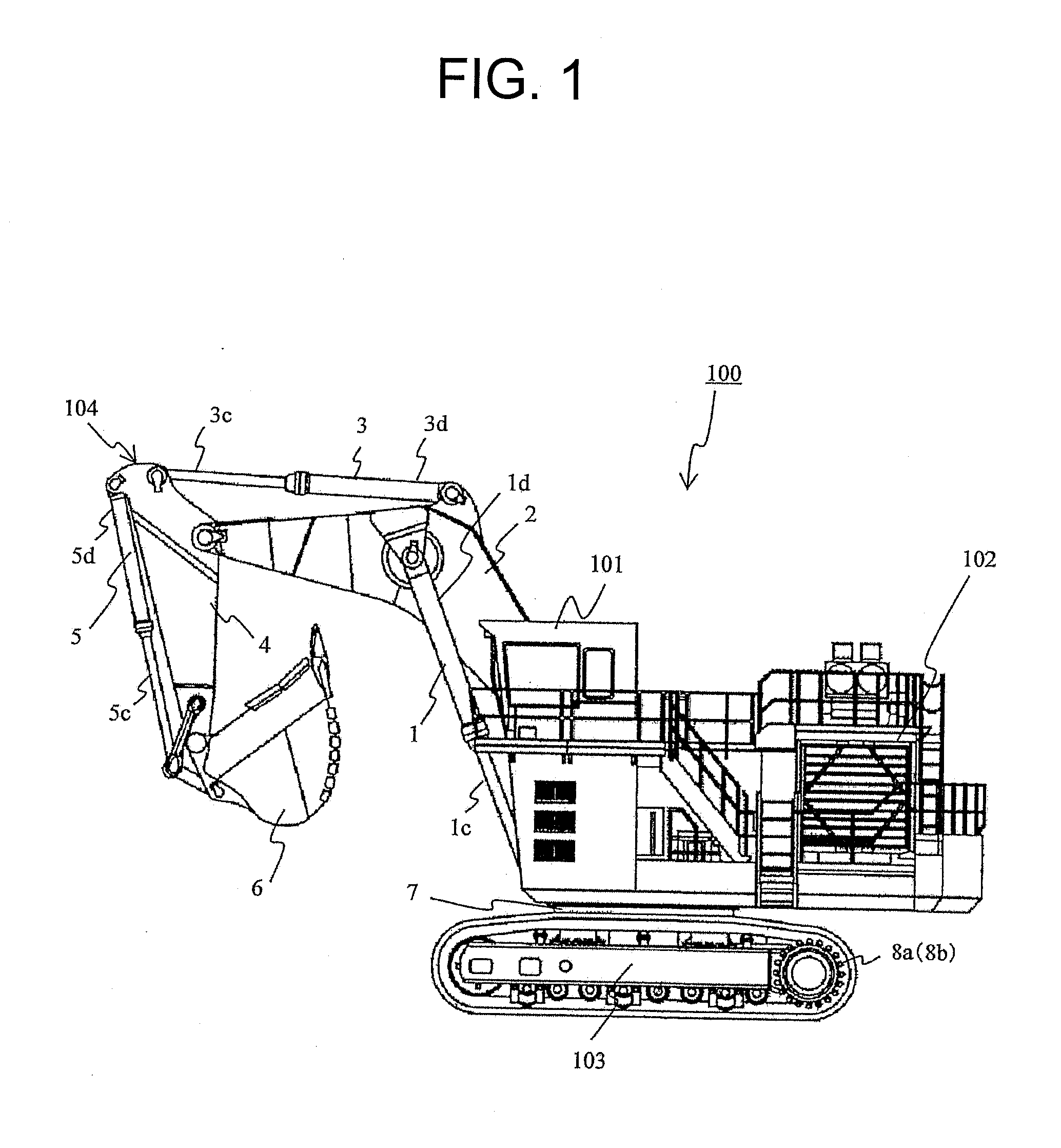
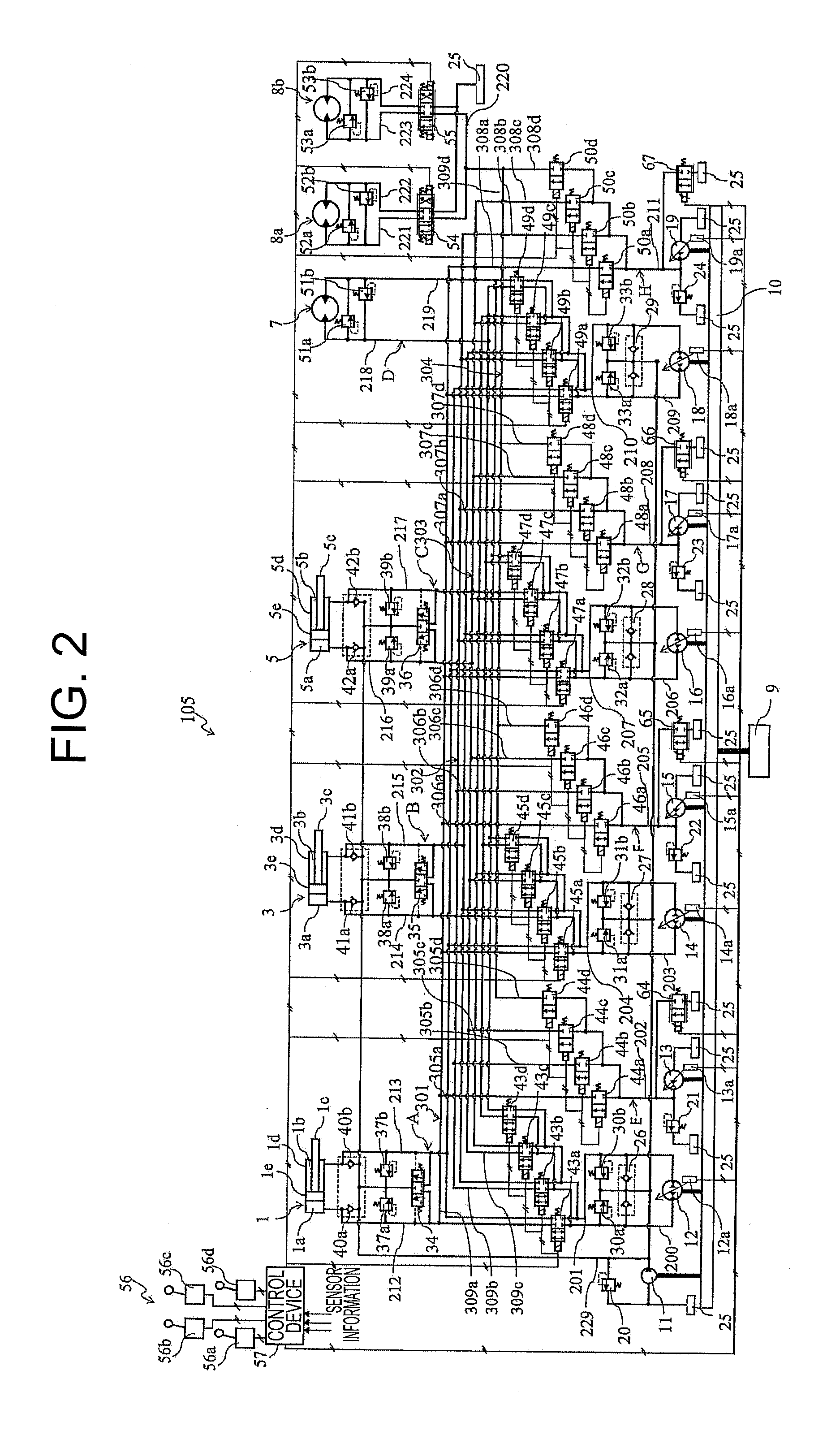
[0031]FIG. 1 is a schematic view showing a hydraulic excavator mounted with a hydraulic driving system according to a first embodiment of the present invention. FIG. 2 is a hydraulic circuit diagram showing a system structure of the hydraulic driving system. In the first embodiment, when a single rod hydraulic cylinder is extended, in order to reduce a pressure difference between the front and rear of a selector valve provided on a flow passage merged with a closed circuit from an open circuit, timing for closing a discharge passage provided in the open circuit in order to discharge hydraulic fluid to a hydraulic fluid tank and timing for opening the selector valve provided on the flow passage to be merged are controlled. Thereby, a change in a hydraulic fluid flow rate with the hydraulic fluid merged into the closed circuit from the open circuit is suppressed, and sufficient starting characteristic of the single rod hydraulic cylinder is achieved. Also, at the same time, when the s...

second embodiment

[0113]FIG. 8 is a schematic view showing a structure of a substantial part of a hydraulic driving system 105A according to a second embodiment of the present invention. The second embodiment differ from the aforementioned first embodiment in that in the first embodiment, the hydraulic driving system 105 is configured with the control device 57 made to serve as the electric circuit, and in contrast, in the second embodiment, the hydraulic driving system 105A is configured with the control device 57 including a hydraulic circuit. Note that in the second embodiment, the same reference signs are used for the parts which are the same as or corresponding to those in the first embodiment.

[0114]Specifically, in the second embodiment, a pilot check valve 500 as a first opening and closing device is provided in a flow passage 202. The pilot check valve 500 normally allows the hydraulic fluid to flow in one direction from the flow passage 202 to a flow passage 305a. When control pressure is ap...

third embodiment

[0123]FIG. 9 is a schematic view showing a structure of a substantial part of a hydraulic driving system 105B according to a third embodiment of the present invention. FIG. 10 is a graph showing extension control timing dT1 with respect to pressure Ph in a flow passage 200 of a closed circuit A of a time difference calculation unit 503c of the hydraulic driving system 105B.

[0124]The third embodiment differs from the aforementioned second embodiment in that in the second embodiment, the hydraulic driving system 105A is configured with the control device 57 including the hydraulic circuit, and in contrast, in the third embodiment, the hydraulic driving system 105B is configured with the control device 57 including a function of calculating extension control timing dT1. Note that in the third embodiment, the same reference signs are used for the parts which are the same as or corresponding to those in the second embodiment.

[0125]The time difference calculation unit 503c of the control ...


PUM


Abstract

To provide a hydraulic driving device configured to smoothly extend a hydraulic cylinder. The present invention includes the open circuit E, the closed circuit A, a control device 57, and a control lever 56a. The open circuit E is provided with a flow passage 202 for connecting an outlet port of the open circuit pump 13 and a head chamber 1a of the boom cylinder 1, a selector valve 44a provided in the flow passage 202, a discharge flow passage 404 for connecting a hydraulic fluid tank 25 and a flow passage 200, and a bleed-off valve 64 provided in the discharge flow passage 404. The control device 57 is configured in such a manner that when a manipulate signal for extending the boom cylinder 1 is input from the control lever 56a, the bleed-off valve 64 is closed, the selector valve 44a is subsequently opened, and the open circuit pump 13 is controlled.

Description

BACKGROUND[0001]1. Field of the Invention[0002]The present invention relates to a hydraulic driving system for driving, for example, an operating machine such as a hydraulic excavator, and especially relates to a hydraulic driving system having a closed circuit with a single rod hydraulic cylinder and a hydraulic fluid inlet-flow and outlet-flow control unit for the closed circuit annularly connected to each other.[0003]2. Description of the Related Art[0004]Recently, in an operating machine such as a hydraulic excavator, a hydraulic circuit referred to as the so-called closed circuit has been known. The closed circuit is configured to be connected annularly (in a closed circuit-shaped manner) so that hydraulic fluid is directly fed to a single rod hydraulic cylinder as a hydraulic actuator from a hydraulic pump as a pressure generation source, and the hydraulic fluid after driving the single rod hydraulic cylinder and performing a predetermined work is directly returned to the sing...

Claims


Application Information

Patent Timeline
Patent Type & Authority Applications(United States)
IPC IPC(8): F15B11/08
CPCF15B2211/46F15B11/08E02F9/2289E02F9/2203E02F9/2225E02F9/2235E02F9/2239E02F9/2285E02F9/2292E02F9/2296F15B7/006F15B11/17F15B2211/20546F15B2211/20561F15B2211/20576F15B2211/27F15B2211/31535F15B2211/40515F15B2211/41581F15B2211/613F15B2211/6346F15B2211/785
Inventor SAITOH, TEPPEISHIMIZU, JURIMIZUOCHI, MARIKOHIRAKU, KENJIISHII, AKINORITAKAHASHI, HIROMASA
Owner NIHON KENKI CO LTD
Why Eureka
Try Eureka