Pure electric automobile chassis system adopting light-weight coach chassis structure

A pure electric vehicle, bus chassis technology, applied in the substructure, vehicle components, transportation and packaging, etc., can solve the problems of lack of adjustability, inconvenient lightweight design, inconvenient multi-layer floor space, etc., to simplify the molding process and assembly process, flexible wheelbase and wheelbase, to achieve the effect of light weight

Inactive Publication Date: 2015-04-08
INST OF DONGGUAN SUN YAT SEN UNIV +1
View PDF8 Cites 27 Cited by
  • Summary
  • Abstract
  • Description
  • Claims
  • Application Information

AI Technical Summary

Problems solved by technology

The dual-space longitudinal beam chassis has the following major defects: 1. The space shape of the longitudinal beam is complex and difficult to form; 2. It can only be designed as a storage type chassis, which is difficult to support the load-carrying body structure; 3. The hardware supporting the front suspension system The point position and angle are fixed, the front and rear axle positions are fixed, lack of adjustability, and it is difficult to support the development of serialized products
[0004] The automobile chassis in the prior art is generally an all-steel single-layer chassis, which is not suitable for electric vehicles driven by new energy sources. On the one hand, the chassis is heavy, which is not convenient for lightweight design; It is convenient to set up multi-layer floor space, and it is necessary to open up additional space for accommodating batteries and motors, occupying the position of the chassis

Method used


Image

  • Pure electric automobile chassis system adopting light-weight coach chassis structure
  • Pure electric automobile chassis system adopting light-weight coach chassis structure
  • Pure electric automobile chassis system adopting light-weight coach chassis structure

Examples


Embodiment 1

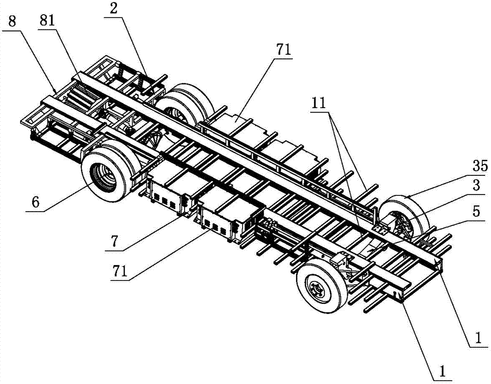
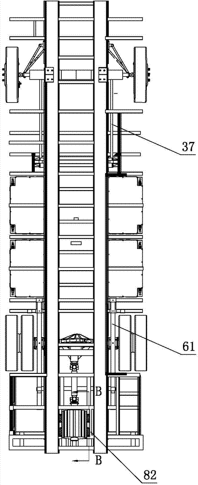
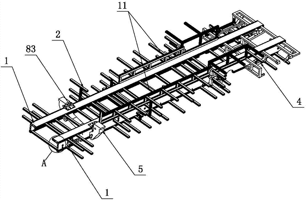
[0042] Such as Figure 1 to Figure 5 , Figure 9 to Figure 11 As shown, a pure electric vehicle chassis system adopting a lightweight bus chassis structure of the present invention includes two longitudinal girders 1 and a plurality of cross beams 11, and a plurality of cross girders 11 are distributed at different height levels and different longitudinal positions of the two longitudinal girders 1 , several beams 11 are tenon-jointed with two longitudinal girders 1 to form an integrally stressed double longitudinal beam 82 multi-layer chassis frame 2; the front part of the double longitudinal beam 82 multi-layer chassis frame 2 is connected with a front bridge 5, and The bridge frame 5 is fixed by two longitudinal girders 1; the rear portion of the double longitudinal girder 82 multi-layer chassis frame 2 is connected with a rear bridge frame 4; the rear bridge frame 4 is fixed by two longitudinal girders 1; the front bridge frame 5 The front axle assembly 3 is connected, th...

Embodiment 2

[0057] Such as Image 6 As shown, the difference between this embodiment and the first embodiment is that the number of the front cantilever 41 and the rear cantilever 42 is two, the two front cantilever beams 41 are distributed horizontally or vertically, and the two cantilever beams 41 are distributed horizontally or vertically. The rear cantilever beams 42 are distributed horizontally or vertically, a front span beam 45 is connected between the two front cantilever beams 41, and a rear span beam 46 is connected between the two rear cantilever beams 42. The front lug seats 43, The rear lug seats 44 are correspondingly arranged on the front span beam 45 and the rear span beam 46 respectively.

[0058] Adopting the rear bridge frame 4 of a plurality of front cantilever beams 41 and rear cantilever beams 42 structures can further improve the connection strength of the rear bridge frame 4, and provide high-strength support points for the installation of the rear axle assembly 6....

Embodiment 3

[0061] Such as Figure 7~Figure 8 As shown, the difference between this embodiment and the second embodiment is that, as a preference, the number of the front cantilever beams 41 and the rear cantilever beams 42 is four respectively, and each of the four front cantilever beams 41 and the four rear cantilever beams 42 is font distribution, a front span beam 45 is connected between two adjacent front cantilever beams 41, a rear span beam 46 is connected between two adjacent rear cantilever beams 42, the front hanging ear seat 43, the rear hanging The ear sockets 44 are correspondingly arranged on the front span beam 45 and the rear span beam 46 respectively. Further, this embodiment adopts the structure of the front cantilever beam 41 and the rear cantilever beam 42 structure in the shape of a square, and further improves the connection strength of the rear bridge frame 4 on the basis of the second embodiment, so as to provide high strength for the installation of the rear axle ...


PUM


Abstract

The invention relates to the technical field of automobiles, in particular to a pure electric automobile chassis system adopting a light-weight coach chassis structure. The pure electric automobile chassis system comprises two longitudinal girders and a plurality of cross beams, wherein the plurality of cross beams are distributed at different-height layer surfaces and different longitudinal positions of the two longitudinal girders and are connected with the two longitudinal girders in a tenoning mode to form an internally-stressed dual-longitudinal-girder multilayer chassis frame; the front part of the dual-longitudinal-girder multilayer chassis frame is connected with a front axle carrier; the front axle carrier is fixed by virtue of the two longitudinal girders; the rear part of the dual-longitudinal-girder multilayer chassis frame is connected with a rear axle carrier which is fixed by virtue of the two longitudinal girders; the front axle carrier is connected with a front axle assembly, and the rear axle carrier is connected with a rear axle assembly; the dual-longitudinal-girder multilayer chassis frame is provided with a drive assembly and an energy assembly. The overall structure of the longitudinal girders is good in rigidity; a processing of assembling the front and rear axle carriers and the chassis frame is simplified, connection is reliable, and integral stress is realized; by virtue of a multilayer floor structure, installation of batteries and motors is convenient and the chassis space is saved.

Description

technical field [0001] The invention relates to the technical field of automobiles, in particular to a pure electric vehicle chassis system adopting a lightweight bus chassis structure. Background technique [0002] Whether it is a traditional car or a new energy vehicle, the lightweight of the body has become a research hotspot, especially for electric vehicles, the significance of lightweight is greater, and the requirements for lightweight are higher. In order to achieve a significant lightweight effect, it is necessary to find new solutions in terms of materials, structures and manufacturing processes. [0003] Most of the existing cars adopt the double-space longitudinal beam chassis load-bearing structure, and a series of installation points are arranged on the longitudinal beams for installing chassis components and compartments. Therefore, the two longitudinal beams are not only the installation base parts, but also the main force-bearing structural parts. The dual-...

Claims


Application Information

Patent Timeline
Patent Type & Authority Applications(China)
IPC IPC(8): B62D21/02
CPCB62D21/02
Inventor 宗志坚周江骆贤宗龙飞永何志昌张永安
Owner INST OF DONGGUAN SUN YAT SEN UNIV
Why Eureka
Try Eureka