System, method and device for coding and decoding
An encoding system and encoding technology, applied in the field of encoding and decoding, can solve the problems of inability to achieve compression, low compression ratio, and inability to compress, and achieve the effect of high compression efficiency and low complexity
- Summary
- Abstract
- Description
- Claims
- Application Information
AI Technical Summary
Problems solved by technology
Method used
Image

Examples
Embodiment 1
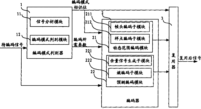
[0048] figure 1 It is a structural schematic diagram of an embodiment of the present invention, such as figure 1 As shown, the encoding system includes an encoding mode discriminator 1 , an encoder 2 and a multiplexer 3 . Wherein, the coding mode discriminator 1 is used to judge the coding mode that the signal to be coded should adopt according to the dynamic range of the signal to be coded, the estimated value of the number of bits required for coding in the predictive coding mode, and the estimated value of the number of bits required for coding in the dynamic range coding mode, and generate And send the encoding mode identification bit corresponding to the encoding mode and the corresponding encoding required parameters to the encoder 2 and the multiplexer 3; the encoder 2 is used to encode the signal to be encoded according to the encoding mode identification bit corresponding to the encoding mode; The multiplexer 3 is used to multiplex the signals encoded by the encode...
Embodiment 2
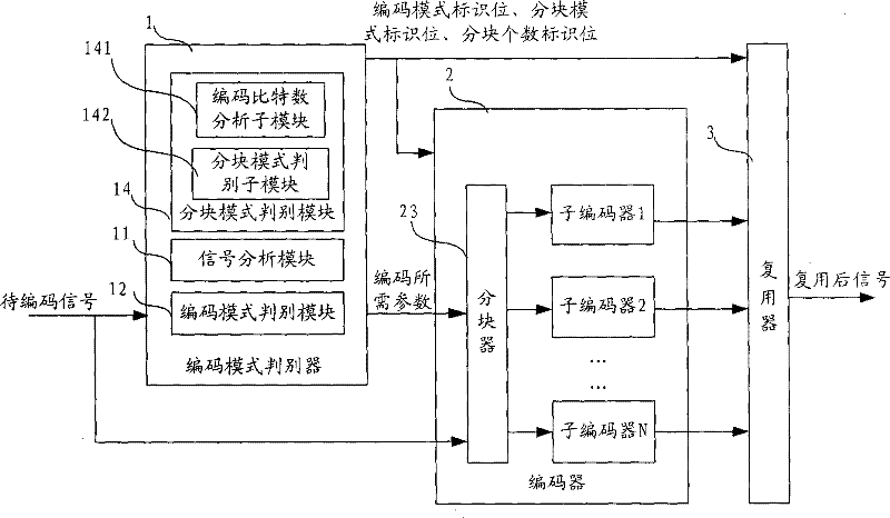
[0060] figure 2 It is a structural schematic diagram of an embodiment of the present invention, such as figure 2 As shown, the difference between the embodiment of the present invention and the first embodiment of the encoding system of the present invention is that the encoding mode discriminator 1 in the embodiment of the present invention also includes a block mode discriminant module 14, which is used to identify the signal to be encoded. Blocking mode, calculate the number of blocks of the signal to be encoded, generate and send the block mode identification bit corresponding to the block mode and the block number identification bit corresponding to the number of blocks to the encoder 2 and the multiplexer 3. The encoder 2 further includes a blocker 23, configured to block the signal to be encoded according to the block mode identification bit and the block number identification bit. Because the signal to be encoded is divided into blocks in the embodiment of the prese...
Embodiment 3
[0099] On the basis of the second embodiment, in order to improve the coding efficiency of the long signal, in the embodiment of the present invention, judging the coding mode that should be used for the signal to be coded also includes judging the block mode that should be used for the signal to be coded, and calculating the partitioning mode of the signal to be coded. The number of blocks, generating and sending the block mode identification bit corresponding to the block mode and the block number corresponding to the number of blocks. Specifically:
[0100] Analyze the number of bits required for single-block encoding and the number of bits required for multi-block encoding of the signal to be encoded according to the encoding mode discriminated by the encoding mode discriminator, and determine the relationship between the two;
[0101] If the former is not greater than the latter, that is, it is judged that the signal to be encoded is a single block encoding mode, then gen...
PUM
 Abstract
Description
Claims
Application Information
 - R&D Engineer
- R&D Manager
- IP Professional
- Industry Leading Data Capabilities
- Powerful AI technology
- Patent DNA Extraction
Browse by: Latest US Patents, China's latest patents, Technical Efficacy Thesaurus, Application Domain, Technology Topic.
© 2024 PatSnap. All rights reserved.Legal|Privacy policy|Modern Slavery Act Transparency Statement|Sitemap