Imaging device

A camera device and image technology, applied in image communication, television, instruments, etc., can solve the problem of undisclosed face images imported into the zoom area and other problems, and achieve the effect of ensuring the tracking range

Inactive Publication Date: 2009-09-30
株式会社炫快丽
View PDF1 Cites 10 Cited by
  • Summary
  • Abstract
  • Description
  • Claims
  • Application Information

AI Technical Summary

Problems solved by technology

[0006] Although Patent Document 1 discloses that the face detection area is set wider than the zoom area, it does not disclose any proposal for introducing a face image into the zoom area.

Method used


Image

  • Imaging device
  • Imaging device
  • Imaging device

Examples


no. 1 Embodiment

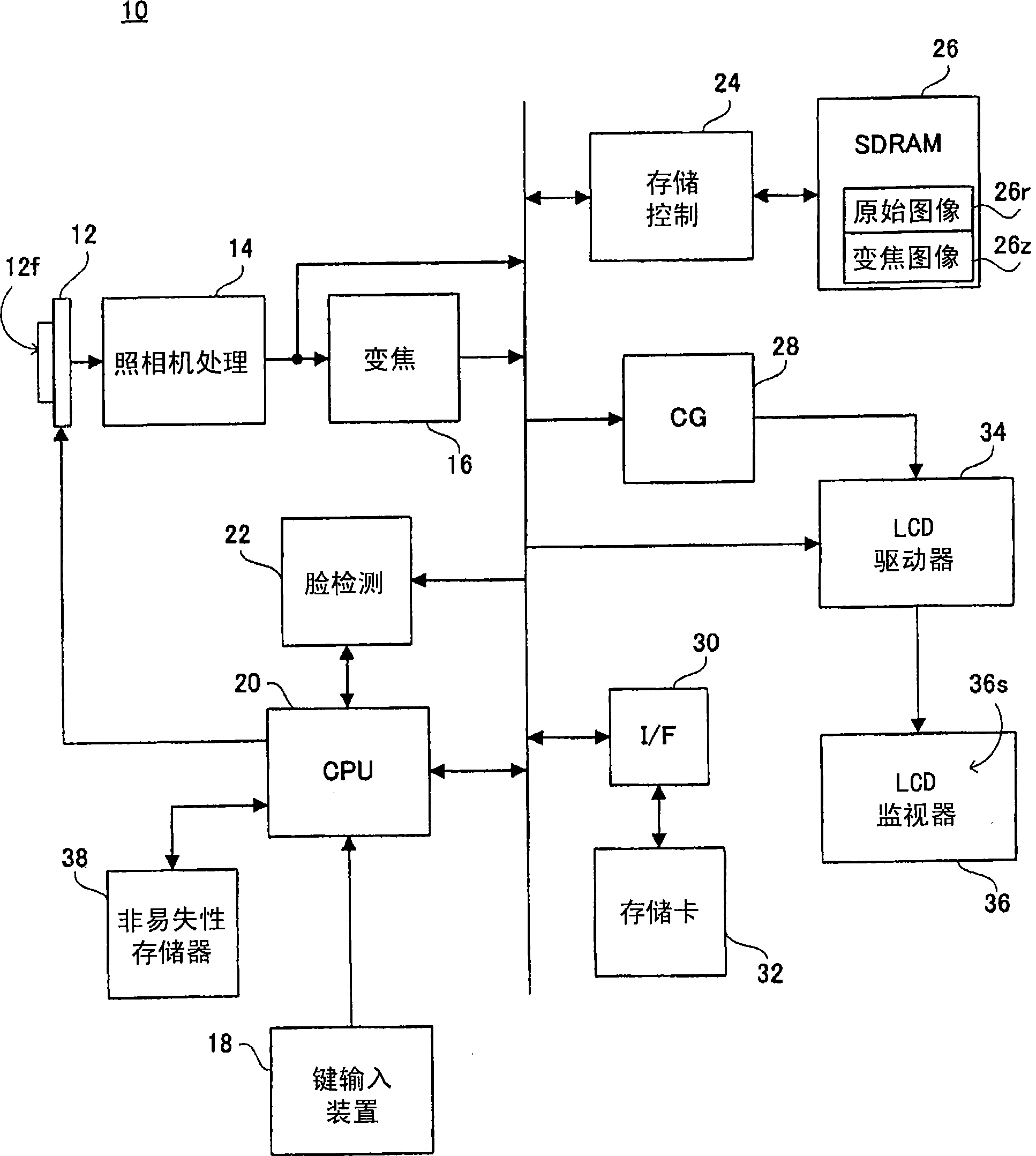
[0065] refer to figure 1 , the digital camera 10 of this embodiment includes an image sensor 12 . An optical image of the captured field of view is irradiated onto the image sensor 12 . In the imaging area 12f of the image sensor 12, for example, a light receiving element of 1600 × 1200 pixels is included, and in the imaging area 12f, an original image of 1600 × 1200 pixels is generated by photoelectric conversion corresponding to the charge of the optical image of the imaging field of view. Signal.

[0066] When the power is turned on, the CPU 20 instructs the image sensor 12 to repeatedly perform pre-exposure and thinning readout in order to display a real-time moving image of the subject on the LCD monitor 36 , that is, a through image. The image sensor 12 repeatedly performs pre-exposure and thinning readout of an original image signal generated thereby in response to a vertical synchronization signal (Vsync) generated every 1 / 30 second. A raw image signal of low resol...

no. 2 Embodiment

[0114] Since the structure of this embodiment is the same as that of the first embodiment, the figure 1 , and omit the description. The basic operation (normal mode) is also common, and the description is omitted. Although this embodiment is characterized by the "automatic tracking+cutout position display mode", part of this mode is the same as the "face position display mode 2" of the first embodiment, and therefore descriptions of the same parts are omitted. Again, in the following, refer to figure 1 and Figure 11 to Figure 15 .

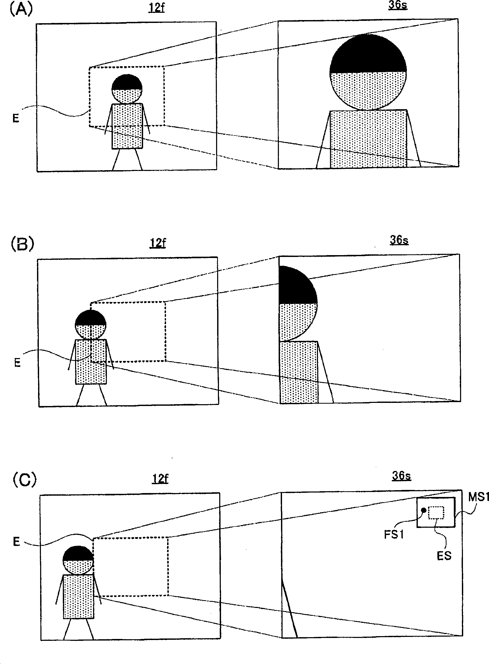
[0115] When utilizing the key input device 18 to select "automatic tracking+cutout position display mode", then directly display the mini-screen MS2 containing the area mark ES representing the position of the zoom area E, and continue this mini-screen until another mode is selected Display of MS2. That is, in this schema, as in Figure 11 (A)~ Figure 11 As shown in (C), the mini screen MS2 is always displayed regardless of the positiona...

no. 3 Embodiment

[0131] Since the structure of this embodiment is the same as that of the first embodiment, the figure 1 , and omit the description. The basic operation (normal mode) is also common, and description is omitted. Although this embodiment is characterized by the "face orientation display mode", part of this mode is the same as the "face position display mode 1" of the first embodiment, and description of the same parts will be omitted. Again, refer to the following figure 1 and Figure 16 ~ Figure 20 .

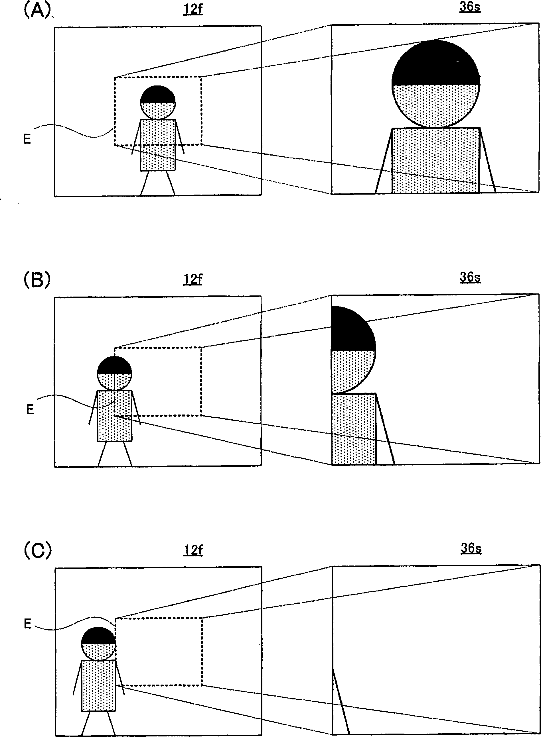
[0132] When using key input device 18 to select "face direction display mode", then as Figure 16 (A)~ Figure 16 As shown in (C), when the face image of interest appears outside the monitor screen 36s, an arrow mark Ar indicating the direction in which the face image exists is displayed on the monitor screen 36s.

[0133] Specifically, first, as Figure 17 As shown in (A), the portion of the imaging field of view corresponding to the imaging area 12 f other than the zoom...


PUM


Abstract

The present invention provides a digital camera (10) which includes an image sensor (12), and by utilizing this, an optical image of an object scene is repeatedly captured. A partial object scene image belonging to a zoom area (E) of the object scene image produced by the image sensor (12) is subjected to zoom processing by a zooming circuit (16), and the obtained zoomed object image is displayed on a monitor screen of an LCD (36) by an LCD driver (34). A CPU (20) detects a facial image (S7, S29) from the produced object scene image through a face detecting circuit (22), and displays the position information indicating the calculated position of the detected facial image with respect to the zoom area (E) on a mini-screen (MS1) within the monitor screen (36s) by controlling a character generator (28) and the LCD driver (34). Hereby, the facial image can be stably transmitted to the zoom area.

Description

technical field [0001] The present invention relates to an imaging device, and particularly, for example, to an imaging device having an electronic zoom function and a face detection function. Background technique [0002] An example of such a device is disclosed in Patent Document 1. In this background art, a zoom area within video data is changed in magnification, and the video data of the zoom area after the magnification change is displayed and recorded. In addition, the multiplier is changed for the face detection area in the video data, the face of the person is detected based on the video data of the multiplied face detection area, and the focus adjustment and white balance control are performed according to the detection result. At this time, by setting the face detection area narrower than the entire area of ​​video data and wider than the zoom area, the accuracy of focus adjustment and white balance control can be improved. [0003] Patent Document 1 JP Unexamine...

Claims


Application Information

Patent Timeline
Patent Type & Authority Applications(China)
IPC IPC(8): H04N5/232G06K9/00
CPCH04N5/23296H04N5/23293H04N5/23219H04N23/61H04N23/611H04N23/635H04N23/69
Inventor 齐藤谕腰山诚司
Owner 株式会社炫快丽
Why Eureka
Try Eureka