Release paper recovering device

A recycling device and release paper technology, which is applied in the directions of transportation and packaging, sending objects, and thin material handling, etc., can solve the problems of poor vacuum, sticking to the baffle 31 on the side wall of the recycling station 3, etc., and achieves the improvement of recycling efficiency. Effect

Inactive Publication Date: 2009-10-07
AU OPTRONICS (XIAMEN) CORP +1
View PDF0 Cites 4 Cited by
  • Summary
  • Abstract
  • Description
  • Claims
  • Application Information

AI Technical Summary

Problems solved by technology

Theoretically, the vacuum roller 1 should drive the release paper 2 to rotate counterclockwise and fall into the recycle bin 3, but if there is glue on the release paper 2, the release paper 2 may stick to it after being blown by the air jet hole 12. On the baffle plate 31 of recycle bin 3 sidewalls (a

Method used


Image

  • Release paper recovering device
  • Release paper recovering device
  • Release paper recovering device

Examples


Embodiment Construction

[0013] In order to have a further understanding of the purpose, structure, features, and functions of the present invention, the following detailed descriptions are provided in conjunction with the embodiments.

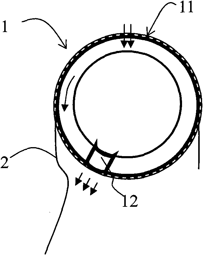
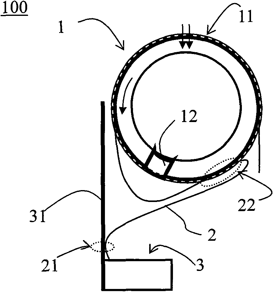
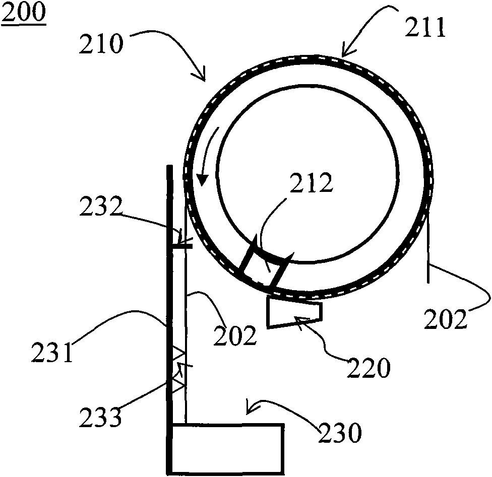
[0014] See image 3 , image 3 It is a schematic diagram of a release paper recovery device 200 according to an embodiment of the present invention. The release paper recycling device 200 includes a vacuum roller 210 and an anti-winding part 220 . The vacuum roller 210 includes a plurality of vacuum suction nozzles 211 and air jet holes 212. These vacuum suction nozzles 211 adsorb the release paper 202 on the vacuum roller 210. The vacuum roller 210 drives the release paper 202 to rotate. The air jet holes 212 are set On the obliquely lower side of the vacuum roller 210, and blow air outward. The anti-winding portion 220 is disposed on the side of the vacuum roller 210 to prevent the release paper 202 blown away from the vacuum roller 210 through the air injection ...


PUM


Abstract

A release paper recovering device comprises a vacuum roller and an anti-wind part. The vacuum roller comprises a plurality of vacuum slots and blowholes, wherein the vacuum slots absorb the release paper on the vacuum roller and the vacuum roller drives the release paper rotate and the blowholes are set at the inclined down side of the vacuum roller and blow air outwards. The anti-wind part is set on the side edge of the vacuum roller for preventing the release paper blown away from the vacuum roller by the blowholes from closing in the vacuum roller again. The release paper is prevented from being twisted into the vacuum roller due to being adhered on a baffle, therefore the recovery is increased.

Description

technical field [0001] The present invention relates to a release paper recovery device, in particular to a release paper recovery device with the performance of an anti-adhesive side wall and an anti-winding recovery wheel. Background technique [0002] Anisotropic conductive tape (ACF) has been widely used in the high-density lead connection between the display screen and the circuit board. There is usually a peelable release paper on one or both sides of the ACF adhesive layer to protect the ACF. and anti-adhesion effect. [0003] In the prior art, vacuum rollers are generally used to recycle the used ACF release paper. See figure 1 , figure 1 It is a schematic diagram of a vacuum roller 1 in the prior art. The vacuum roller 1 includes a vacuum suction hole 11 and an air jet hole 12. The vacuum suction hole 11 absorbs the release paper 2 on the roller 1. At the same time, the roller 1 drives the release paper 2 to rotate counterclockwise, and the air jet hole 12 blows...

Claims


Application Information

Patent Timeline
IPC IPC(8): B65H41/00
Inventor 张毅
Owner AU OPTRONICS (XIAMEN) CORP
Why Eureka
Try Eureka