Rotatable self-positioning igniting needle for gas stove and combustor

An ignition needle and self-positioning technology, which is used in household stoves/stoves, applications, and household heating, etc., can solve the problems of inability to seal, the size of the through hole in the middle of the burner is large, and the ignition needle cannot be easily removed, so as to reduce the The effect of small size, few parts and simple structure

Pending Publication Date: 2019-09-06
VATTI CORP LTD
View PDF0 Cites 0 Cited by
  • Summary
  • Abstract
  • Description
  • Claims
  • Application Information

AI Technical Summary

Problems solved by technology

[0003] In view of this, the main purpose of the present invention is to provide a rotatable self-positioning ignition needle for gas stoves, which solves the problem that the needle body of the ignition needle in the prior art cannot be easily removed from the disassembly path of the burner and the double needle The structure leads to the problem that the size of the through hole in the middle of the burner is large and cannot be closed; the purpose of the present invention is also to provide a burner containing the ignition needle

Method used


Image

  • Rotatable self-positioning igniting needle for gas stove and combustor
  • Rotatable self-positioning igniting needle for gas stove and combustor
  • Rotatable self-positioning igniting needle for gas stove and combustor

Examples


Embodiment Construction

[0025] In order to make the object, technical solution and advantages of the present invention clearer, the present invention will be further described in detail below in conjunction with the accompanying drawings and embodiments. It should be understood that the specific embodiments described here are only used to explain the present invention, not to limit the present invention.

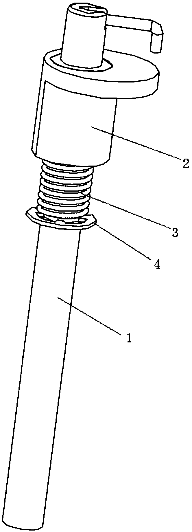
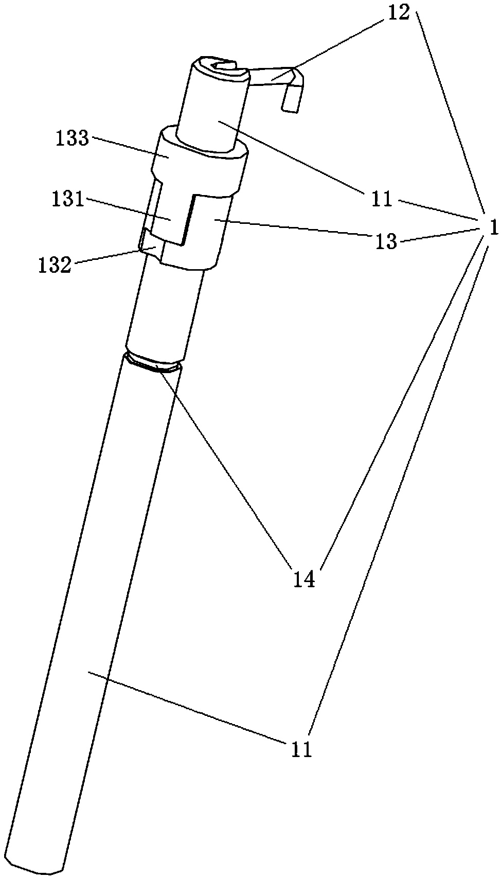
[0026] A rotatable self-positioning ignition needle for a gas stove provided by an embodiment of the present invention, such as figure 1 As shown, it includes a ceramic body component 1, a fixing seat 2, an elastic component 3, and a fixing piece 4. The fixing base 2, the elastic component 3, and the fixing piece 4 are sleeved on the ceramic body component 1 in sequence from top to bottom. Part 4 is fixed on the ceramic body assembly 1, and the elastic assembly 3 axially tensions the ceramic body assembly 1 in the fixing seat 2 through the fixing part 4; wherein, the fixing seat 2 is fixedly instal...


PUM


Abstract

The invention discloses a rotatable self-positioning igniting needle for a gas stove. The rotatable self-positioning igniting needle for the gas stove comprises a ceramic body assembly, a fixing seat,an elastic assembly and a fixing part, wherein the fixing seat, the elastic assembly and the fixing part sequentially sleeves the ceramic body assembly from top to bottom; the fixing part is fixedlyarranged on the ceramic body assembly; the elastic assembly is used for axially tensioning the ceramic body assembly in the fixing seat through the fixing part; at least two positioning grooves are formed in the outer wall of the ceramic body assembly; and positioning pins which fit the positioning grooves are arranged on the inner sidewall of the fixing seat. According to the rotatable self-positioning igniting needle for the gas stove, the igniting needle is of a single-needle structure, and the structure is simple, and few spare parts are needed; the size of a through hole in the middle ofthe combustor can be reduced; the problem that the combustor cannot be conveniently removed due to an igniting needle body; in addition, the needle body in the igniting needle can be circumferentiallyrotated along with the ceramic body assembly, and the circumferential rotating angle is 0-180 degrees, so that the problem that a conductor connected to the lower part of the needle body is rotated without limitation and is knotted can be solved.

Description

technical field [0001] The invention belongs to the technical field of gas stoves, and in particular relates to a rotatable self-positioning ignition needle for a gas stove, a burner and a gas stove. Background technique [0002] Most of the ignition needles on gas stoves on the market are fixed structures. The ignition needles of atmospheric stoves are placed on the side of the fire outlet. Infrared stoves have a large total area of ​​fire holes and a low gas flow rate at the gas outlet. The needle body of the ignition needle is mostly placed above the fire outlet; in order to meet the requirements of easy disassembly and assembly of the infrared burner, the needle body of the ignition needle needs to be easily removed from the disassembly path of the burner. In the prior art, there are rotatable The solution of the ignition needle, but because the ignition needle is a double needle, it requires the size of the middle through hole of the burner to be large and cannot be clo...

Claims


Application Information

Patent Timeline
Patent Type & Authority Applications(China)
IPC IPC(8): F24C3/08F24C3/10
CPCF24C3/085F24C3/10
Inventor 刘凯陈琦罗长兵潘叶江
Owner VATTI CORP LTD
Why Eureka
Try Eureka