Bending die

A technology of bending molds and bending blocks, applied in forming tools, manufacturing tools, metal processing equipment, etc., can solve the problems of low mold debugging efficiency and inconvenient operation

Inactive Publication Date: 2009-10-14
HONG FU JIN PRECISION IND (SHENZHEN) CO LTD +1
View PDF0 Cites 18 Cited by
  • Summary
  • Abstract
  • Description
  • Claims
  • Application Information

AI Technical Summary

Problems solved by technology

Every time the mold clamping gap is adjusted, the upper mold base 12 needs to be removed, and the mold needs to be calibrated again after adjustment, which is not only inconvenient to operate, but also leads to low efficiency of mold debugging

Method used


Image

  • Bending die
  • Bending die
  • Bending die

Examples


Embodiment Construction

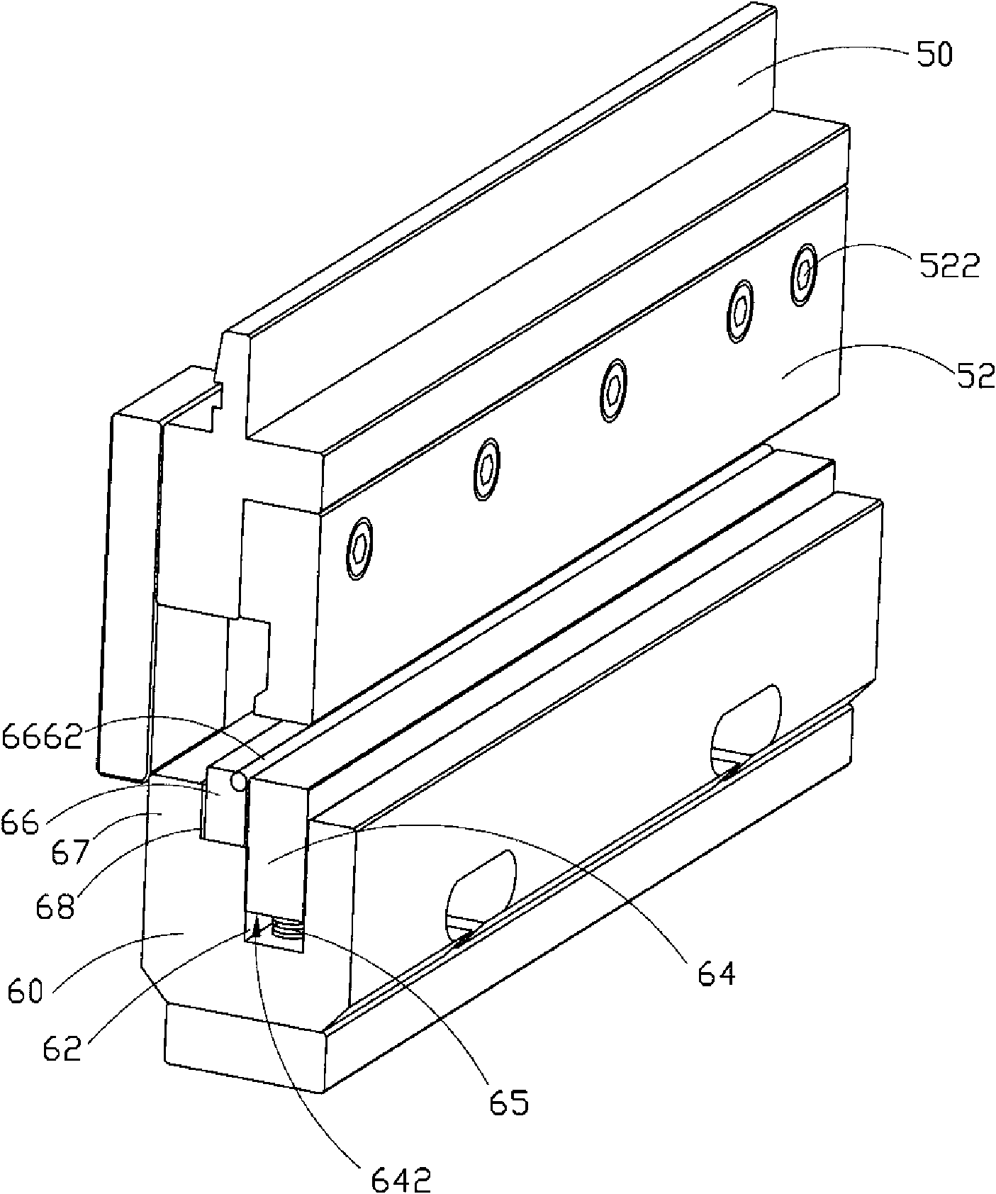
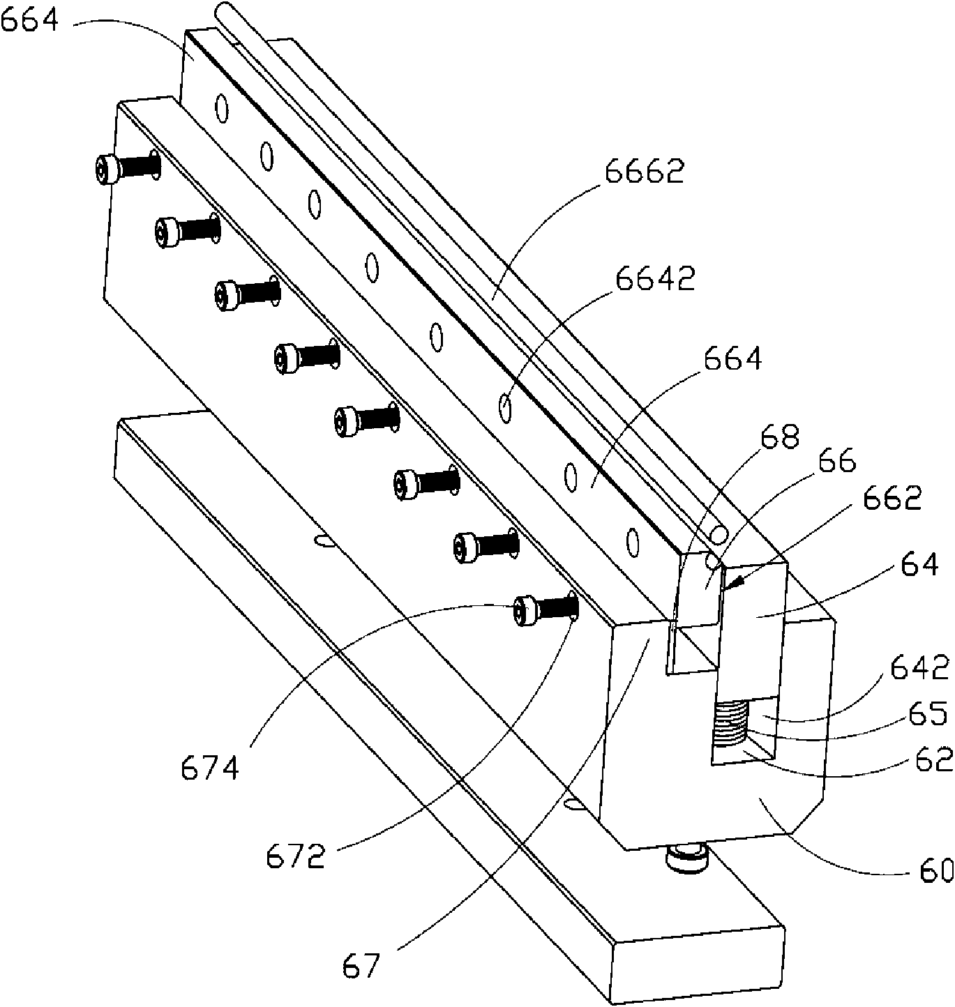
[0014] see figure 2 with image 3 , which shows a bending die in a preferred embodiment of the present invention, the bending die includes an upper mold base 50 and a lower mold body 60, and the upper mold base 50 and the lower mold body 60 are arranged correspondingly up and down On the CNC bending machine (not shown in the figure).

[0015] The cutter head 52 is fixedly connected to the upper mold base 50 by a plurality of screws 522 . The lower mold body 60 is provided with a groove 62 , and the groove 62 is arranged opposite to the cutter head 52 . The stripping block 64 is accommodated in the groove 62, and a spring 65 is arranged between the bottom surface 642 of the stripping block 64 and the lower mold body 60, and the stripping block 64 can be moved relative to the bottom surface 64 by the spring 65. The lower mold body 60 moves elastically. The bending block 66 includes a first side 662 and a second side 664 , the first side 662 is adjacent to the stripping bloc...


PUM


Abstract

The invention relates to a bending die, which comprises an upper die holder capable of fixedly connecting a tool bit, a lower die body arranged opposite to the upper die holder, a withdrawing block, a bending block and a compound gasket. The withdrawing block and the tool bit are arranged oppositely on the lower die body, and can elastically move relative to the lower die body; the bending block comprises a first lateral surface and a second lateral surface, wherein the first lateral surface is abutted with the withdrawing block, and the second lateral surface is connected with the lower die body by a screw thread; and the compound gasket is arranged between the second lateral surface of the withdrawing block and the lower die body and used for adjusting the clearance between the bending block and the withdrawing block. The compound die clearance of the bending die is changed by adjusting the thickness of the compound gasket; when the compound die clearance is adjusted, the die does not need to be detached from a machine tool, and the adjustment can be finished directly on the machine tool; and after the compound die clearance is adjusted, the bending die does not need to be re-corrected.

Description

technical field [0001] The invention relates to a bending die, in particular to a numerical control bending processing molding die. Background technique [0002] The size of the clamping gap of the bending mold is the main factor affecting the precision of the part. The larger the gap, the worse the precision of the part. However, if the gap is too small, it will cause difficulty in drafting or scratches on the surface of the part. Therefore, it is necessary to adjust different clamping clearances for bending different parts. [0003] see figure 1 , is a perspective view of a bending die of the prior art. Described mold comprises patrix 10 and counterdie 20, and described patrix 10 comprises fixed plate 11, patrix 12 and is located at the backing plate 13 between described fixed plate 11 and described patrix 12; The upper mold base 12 is fixedly connected to the cutting tool 14, the lower mold 20 includes a lower mold body 22, and the stripping block 23 is elastically con...

Claims


Application Information

Patent Timeline
IPC IPC(8): B21D37/10B21D37/12B21D11/00
CPCB21D5/04
Inventor 黄国荣刘以华黄福顺周述伟罗健
Owner HONG FU JIN PRECISION IND (SHENZHEN) CO LTD
Why Eureka
Try Eureka