Elevator
A technology of elevators and cars, applied in elevators, transportation and packaging, etc., can solve problems such as difficult car operations, and achieve the effect of ensuring the working space
- Summary
- Abstract
- Description
- Claims
- Application Information
AI Technical Summary
Problems solved by technology
Method used
Image
Examples
no. 1 approach
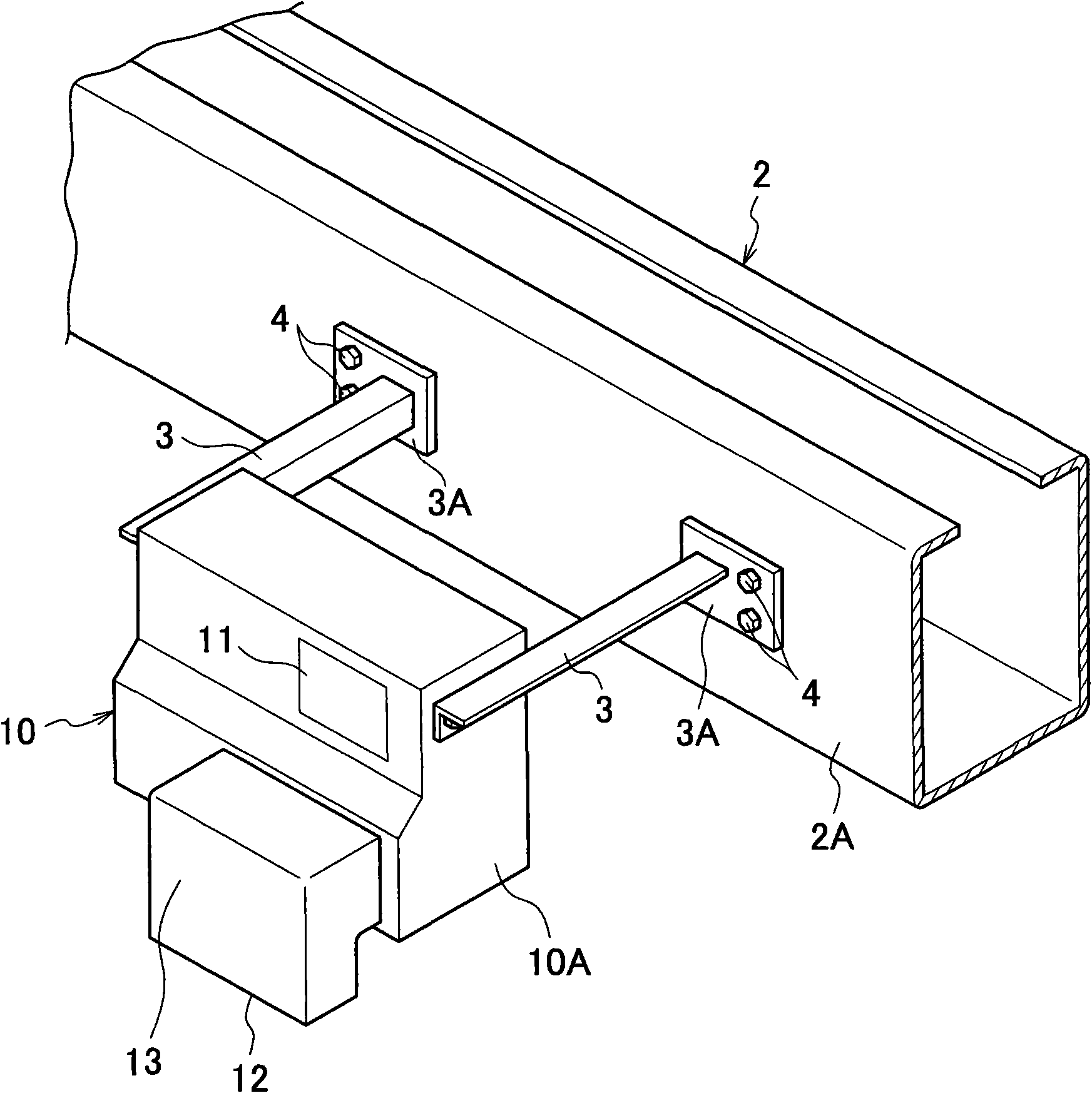
[0039] Figure 3 ~ Figure 7 The main part of the elevator which concerns on 1st Embodiment of this invention is shown. The elevator of the first embodiment applies the present invention to a so-called machine room-less elevator in which a power source is installed in an elevator (not shown).
[0040] Such as image 3 and Figure 4 As shown, the elevator of the first embodiment has an upper beam 2 integrated with the car 1 above the car 1 . In addition to the upper beam 2, the car 1 also has a lower beam (not shown) erected below the car 1, and a column that connects the ends of the lower beam and the upper beam 2 and stands along the side of the car 1. (not shown), etc.
[0041] The upper beam 2 is disposed above the roof 1A of the car 1 by a predetermined distance, and is erected in the horizontal direction so as to pass through the center of the roof 1A. The upper beam 2, the lower beam, and the column are formed of reinforced steel materials such as C-shaped steel.
...
no. 2 approach
[0049] Figure 8 and Figure 9 The main part of the elevator which concerns on 2nd Embodiment of this invention is shown.
[0050]In the elevator of the second embodiment, the work platform 20 is separately attached to the air conditioner 10 . Except for this structure, the second embodiment is the same as the first embodiment. Therefore, the same symbols are used for the same parts and descriptions are omitted.
[0051] In the second embodiment, as Figure 8 As shown, the flange portion 3A of the mounting rod 3 is fixed to the lower portion of the side surface 2A of the upper beam 2 with bolts 4 and nuts. A flange portion 8A provided at one end of a table rod (table support rod) 8 is fixed to a side surface 2A of the upper beam 2 above the flange portion 3A of the mounting rod 3 with bolts 9 and nuts.
[0052] The pair of table poles 8 are the same member as the mounting pole 3 and have the same length as the mounting pole 3 . The workbench pole 8 is parallel to the mou...
no. 3 approach
[0062] Figure 14 The third embodiment of the present invention is shown. Since the third embodiment has a structure similar to that of the first embodiment, the same parts as those of the first embodiment are denoted by the same symbols and descriptions thereof are omitted.
[0063] In the third embodiment, if Figure 14 As shown, the mounting rod 3 is set slightly longer. The workbench 29 is erected on the mounting rod 3 on the side of the upper beam 2 of the air conditioner 10 and on the side of the air conditioner 10 opposite to the upper beam 2 . In the area between these workbenches 29, the upper surface of the air conditioner 10 is exposed. In this way, by exposing the upper surface of the air conditioner 10 , the operator can easily detach the top plate of the air conditioner 10 from the upper part of the air conditioner 10 and carry out inspection work while riding on the workbench 29 .
[0064] (Modification of the third embodiment)
[0065] Figure 15 A modifi...
PUM
 Abstract
Description
Claims
Application Information
 - R&D
- Intellectual Property
- Life Sciences
- Materials
- Tech Scout
- Unparalleled Data Quality
- Higher Quality Content
- 60% Fewer Hallucinations
Browse by: Latest US Patents, China's latest patents, Technical Efficacy Thesaurus, Application Domain, Technology Topic, Popular Technical Reports.
© 2025 PatSnap. All rights reserved.Legal|Privacy policy|Modern Slavery Act Transparency Statement|Sitemap|About US| Contact US: help@patsnap.com


