Work device and emergency release system

一种应急下降、工作机的技术,应用在移土机/挖土机、上部结构、载荷吊挂元件等方向,能够解决驾驶室倾斜度改变、危及操作者等问题,达到简单结构、安全且可靠启动的效果

Active Publication Date: 2009-10-14
LEIBHERR HYDRAULIKBAGGER GMBH
View PDF1 Cites 3 Cited by
  • Summary
  • Abstract
  • Description
  • Claims
  • Application Information

AI Technical Summary

Problems solved by technology

[0005] However, in known working machines there is the problem that the inclination angle of the cab relative to the attachment means on the cab boom is limited by the tilt adjustment means so that in the event of an emergency descent when the cab boom turns downwards , the inclination of the cab changes
As a result, the cab may have a considerable slope when lowering, thereby endangering the operator

Method used


Image

  • Work device and emergency release system
  • Work device and emergency release system
  • Work device and emergency release system

Examples


Embodiment Construction

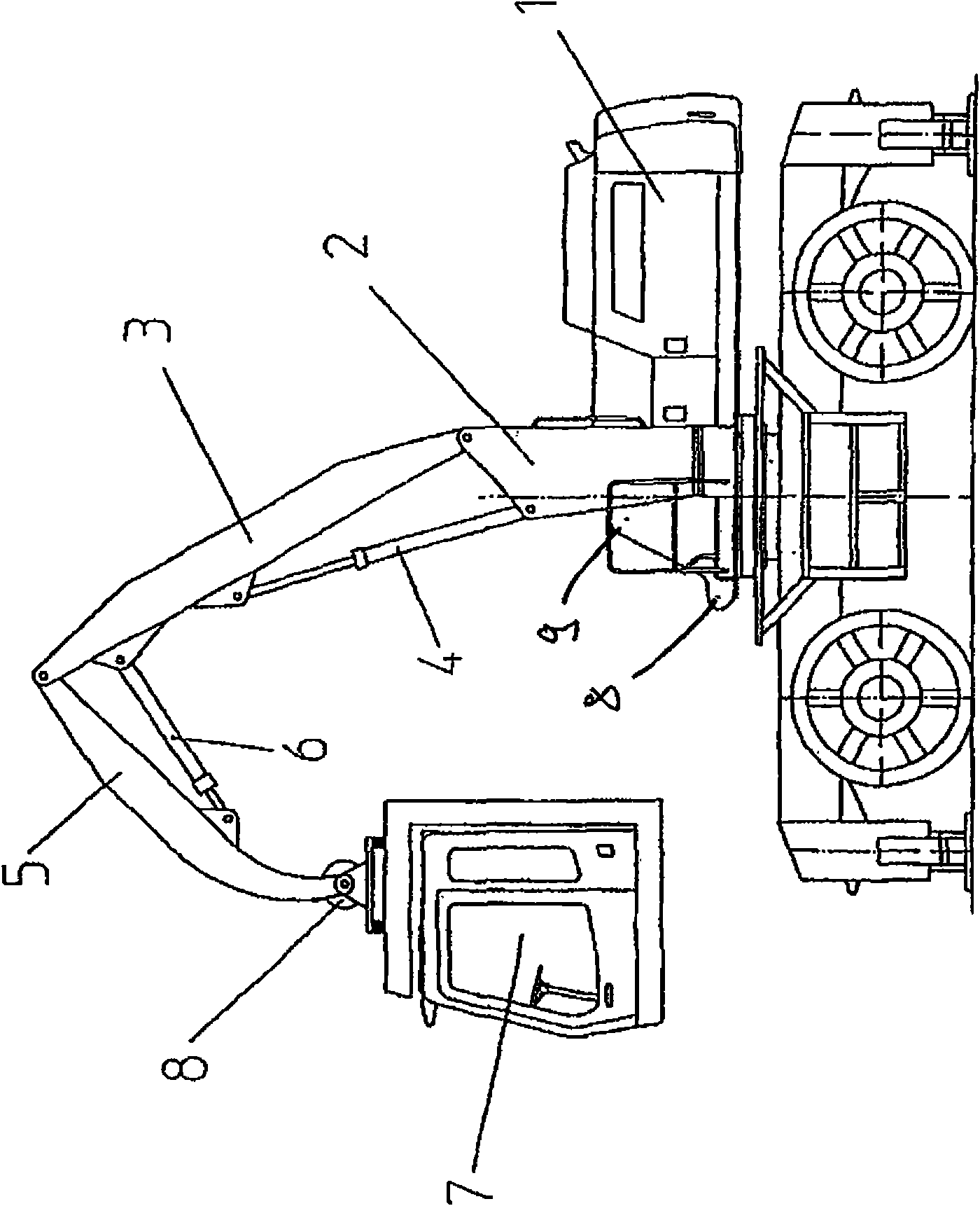
[0021] figure 1 An embodiment of a working machine according to the invention is shown. The working machine includes a movable bottom frame with an upper frame 1 mounted on the bottom frame in a manner capable of rotating around a vertical rotation axis, and the movable bottom frame and the upper frame 1 form a host. figure 1 A working boom, not shown in the figure, is usually pivotally mounted to the main machine. The working boom includes working tools such as buckets, grabs or hooks, and the working booms can be used for material handling, for example. in figure 1 In the embodiment shown in the figure, the working boom not shown in the figure can be pivotally mounted to the pivot points 8 and 9 of the upper frame 1. The working machine can be, for example, a material handler, crane or excavator for wood, waste or any other goods, especially hydraulic excavators.

[0022] The working machine includes a cab 7 from which the operator operates the working machine. The cab 7 is ...


PUM


Abstract

The present invention relates to a working machine, in particular to a traveling material-handling machine, especially to a hydraulic excavator, comprising a basic machine, a cabin and a cabin arm pivotally mounted on the basic machine, by means of which the position of the cabin with respect to the basic machine can be varied, wherein the cabin arm can be swivelled with respect to the basic machine about a horizontal axis by means of at least one hydraulic actuator, and wherein the cabin is pivotally mounted on the cabin arm via a hydraulic inclination adjustment device. In accordance with the invention, the cabin includes an emergency lowering system, in which an inclination emergency valve is provided for the inclination adjustment device of the cabin, which in a case of emergency lowering provides for alignment of the cabin into a normal position.

Description

Technical field [0001] The invention relates to a working machine, particularly a mobile material handling machine, especially a hydraulic excavator, which includes a main engine, a cab and a cab cantilever pivotally mounted on the main frame. The relative position of the cab can be changed by the cab cantilever. In the position of the main engine, the cab cantilever can rotate relative to the main engine about a horizontal axis through at least one hydraulic actuator, and the cab is pivotally mounted to the cab cantilever via a hydraulic tilt adjustment device. Background technique [0002] Such a working machine is known from DE 20 2004 019 708 U1. [0003] In this working machine, the position of the cab relative to the host can be changed through the cantilever of the cab, so that the operator always has the best view of the working area and / or tools of the working machine. When the cab cantilever rotates, the cab tilts relative to the cab cantilever without corresponding cha...

Claims


Application Information

Patent Timeline
Patent Type & Authority Applications(China)
IPC IPC(8): E02F9/16E02F9/24B66C13/54
CPCE02F9/2217E02F9/226B62D33/0617E02F9/166B66C13/54B62D33/063
Inventor 西蒙·迈尔
Owner LEIBHERR HYDRAULIKBAGGER GMBH
Why Eureka
Try Eureka