
Tension adjusting device for belt

A technology for adjusting device and belt tension, which is applied in the direction of transmission device, belt/chain/gear, mechanical equipment, etc., and can solve the problems of difficult loading and unloading of belts, time-consuming, laborious, etc.

Inactive Publication Date: 2009-10-14
LITE ON ELECTRONICS (GUANGZHOU) LTD +1
View PDF0 Cites 7 Cited by
  • Summary
  • Abstract
  • Description
  • Claims
  • Application Information

AI Technical Summary

Problems solved by technology

[0003] However, in the prior art, there is a problem that it is difficult to load and unload the belt
Generally speaking, the belt tension adjusting device of this structure requires the use of tools (for example, tools such as screwdrivers) when installing or removing and replacing the belt, so that it is time-consuming and labor-intensive.
What's more, professional maintenance personnel, technicians are required to install or remove and replace the belt

Method used


Image

  • Tension adjusting device for belt
  • Tension adjusting device for belt
  • Tension adjusting device for belt

Examples


Embodiment Construction

[0019] The present invention will be described in detail below with reference to the accompanying drawings. The accompanying drawings are used to explain the present invention in the real-time manner described below, but not to limit the present invention.

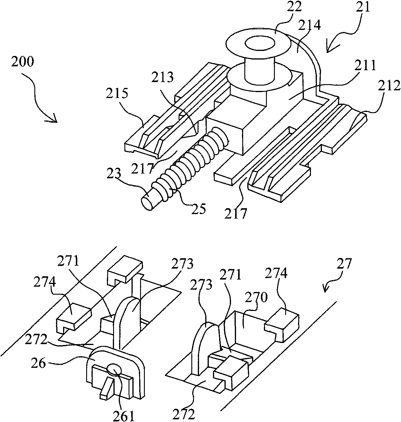
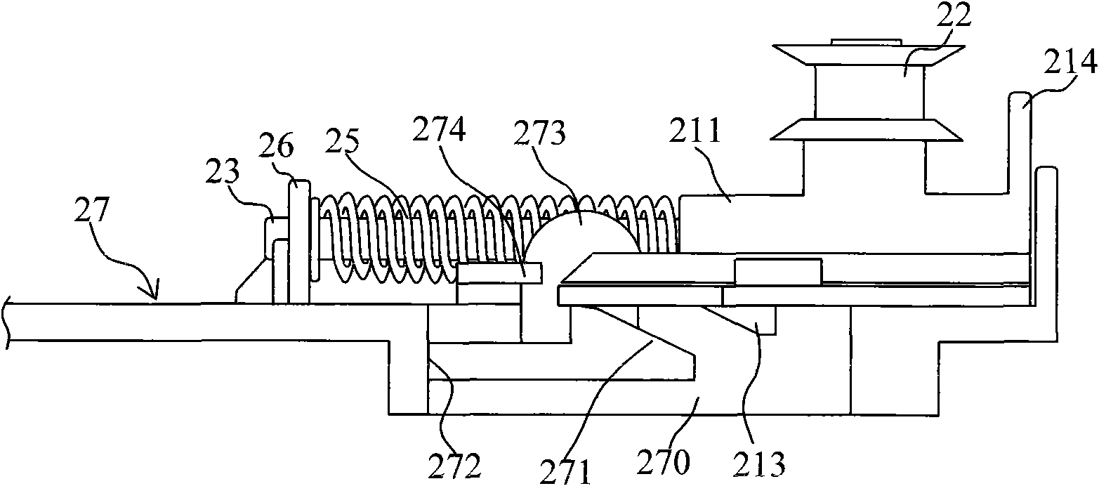
[0020] figure 2 It is an exploded view of the present invention. see figure 2 , an embodiment of the present invention is a belt tension adjusting device 200, the belt tension adjusting device 200 is located and installed on the base 27 of the scanning device. In this embodiment, the elastic control mechanism is mainly composed of a pressing member 273 , an elastic clip 271 and a rigid hook 213 . The elastic force control mechanism can selectively release or accumulate the elastic force of the spring 25, and adjust the distance between the driven wheel 22 and the driving wheel (not shown) to adjust the tension of the belt 24, so as to facilitate the installation and removal of the belt 24.

[0021] In order to install...


PUM


Abstract

The invention provides a tension adjusting device for a belt, which comprises a drive wheel, a driven wheel, the belt, a base, a base frame, a spring and an elasticity control mechanism, wherein the drive wheel is driven by a motor to rotate; the belt is sleeved between the drive wheel and the driven wheel; the base frame is used for supporting the driven wheel and is arranged on the base, and can move on the base; the spring is used for adjusting the tension of the belt; and the elasticity control mechanism is used for selectively releasing or accumulating the elasticity of the spring and regulating the distance between the driven wheel and the drive wheel. The base frame and a position wheel of the driven wheel are locked at proper positions through rigid trips on the base frame and elastic chucks that are matched with the rigid trips and are arranged on the base so that the belt is installed, a pressing piece is pressed after the belt is installed, the elastic chucks separate from the rigid trips, and the belt is tightened. When the belt is dismounted, the base frame is pushed, the elastic chucks are buckled with the rigid trips, the distance between the drive wheel and the driven wheel is shortened, therefore, the belt can be conveniently dismounted. The displacement of the belt is the same as the combination of the dismounting and the mounting of the belt.

Description

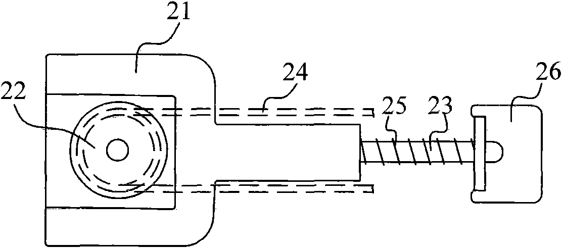
technical field [0001] The invention relates to a belt tensioning device, in particular to a tension adjusting device for reciprocating movement, which can be used in scanning devices and printing devices. Background technique [0002] figure 1 It is a top view of the belt tension adjusting device of the existing scanning equipment. Please refer to figure 1 As shown, the belt tension adjusting device is located and installed on the base of the scanning device, and includes a base frame 21, a driven wheel 22 is arranged on the base frame 21, and a driving wheel (not shown in the figure) . The driving wheel driven by the motor has a certain distance from the driven wheel 22 , and a timing belt 24 is inserted between the driven wheel 22 and the driving wheel to drive the driven wheel to rotate. A guide rod 23 protrudes from the front end of the base frame 21 (that is, the right side in the figure is the front), and the guide rod 23 is covered with a coil spring 25 . On the...

Claims


Application Information

Patent Timeline
IPC IPC(8): F16H7/08
Inventor 陈柏松
Owner LITE ON ELECTRONICS (GUANGZHOU) LTD
Learn More