Led light source device

A technology of light-emitting diodes and radiation devices, which is applied in the direction of display devices, lighting devices, semiconductor devices of light-emitting elements, etc., can solve the problems of irradiation and insufficient illumination, achieve large design freedom, easy light distribution control, prevent The effect of interface reflection

Inactive Publication Date: 2009-10-14
USHIO DENKI KK
View PDF9 Cites 9 Cited by
  • Summary
  • Abstract
  • Description
  • Claims
  • Application Information

AI Technical Summary

Problems solved by technology

That is, in order to make the light-emitting diode light emitting device irradiate light to the irradiated surface having a large area, a plurality of LED packages composed of light-emitting elements and optical members are provided, and these plurality of LED packages are arranged on a common substrate. In the case of the structure, the light cannot be uniformly irradiated on the irradiated surface, and sufficient illuminance cannot be obtained.

Method used


Image

  • Led light source device
  • Led light source device
  • Led light source device

Examples


Embodiment Construction

[0052] Hereinafter, embodiments of the present invention will be described in detail.

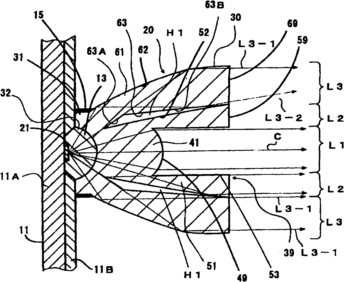
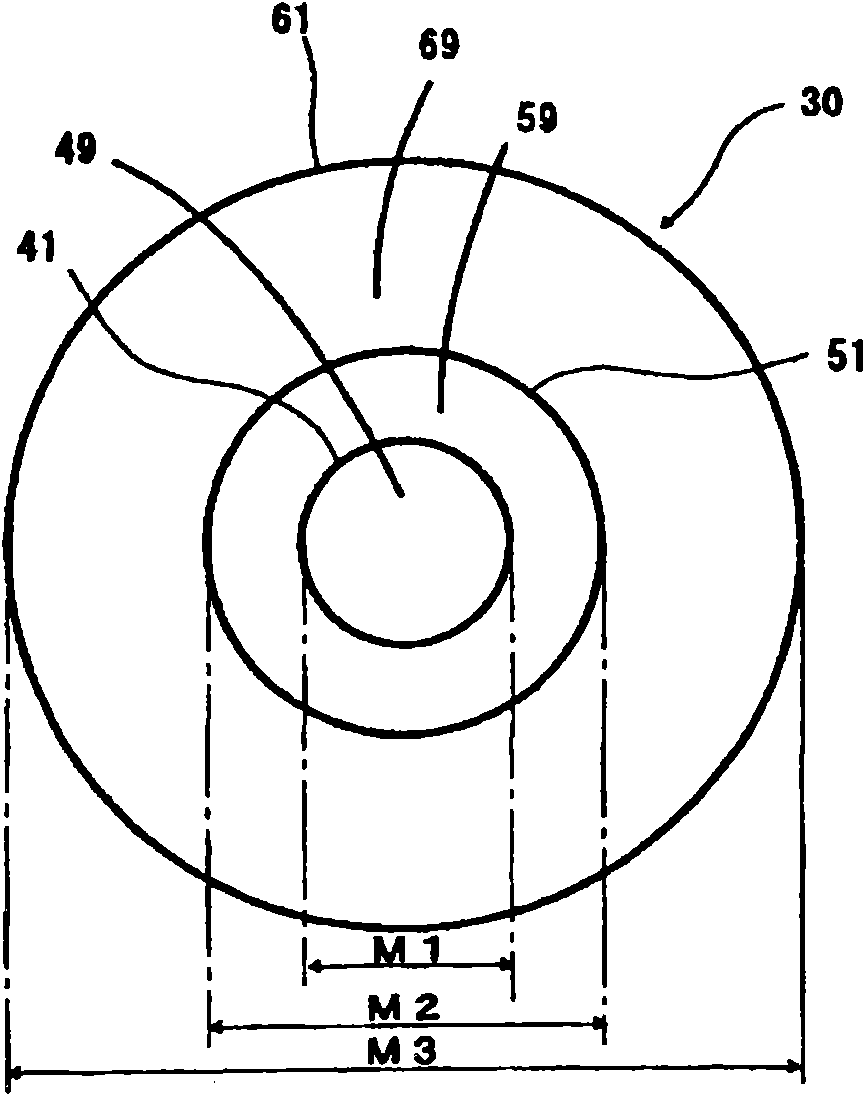
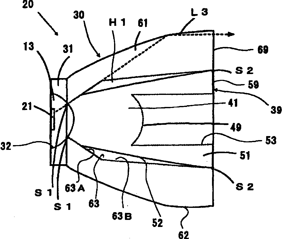
[0053] figure 1 It is an explanatory cross-sectional view showing an example of the structure of the light-emitting diode light emitting device of the present invention, figure 2 yes means figure 1 An explanatory diagram of the light emitting surface of the light emitting diode light emitting device, image 3 is the composition figure 1 An explanatory diagram of the composition of the LED package of the light-emitting diode light emitting device, Figure 4 yes image 3 The front view of the LED package, Figure 5 is enlarged figure 1 Explanation of the main part of the light-emitting diode light emitting device with an enlarged cross-sectional view, Figure 6 is the composition figure 1 An exploded view for explaining the structure of the translucent light guide member of the light emitting diode light emitting device.

[0054] This light-emitting diode light emitting device ...


PUM


Abstract

An LED light source device using light from luminescent elements at a high level of uniformity and efficiency, and to conduct irradiation with a high level of design freedom an LED light source deviceis equipped with luminescent elements and a translucent light-guiding member. The translucent light-guiding member has a central convex lens with a first cylindrical light-guiding part formed on theouter periphery of the central convex lens and a second cylindrical light-guiding part formed on the outer periphery of the first cylindrical light-guiding part, such that an air layer is formed between the outer peripheral surface of the first cylindrical light-guiding part and the inner peripheral surface of the second cylindrical light-guiding part, the outer peripheral surface of the first cylindrical light-guiding part and the outer peripheral surface of the second cylindrical light-guiding part being rotated quadratic surfaces with the same focal point.

Description

technical field [0001] The present invention relates to a light-emitting diode light emitting device, and more specifically, to a light-emitting diode light emitting device that emits light from a light-emitting diode (LED: Light-Emitting Diode) in a predetermined direction and range through an optical member. Background technique [0002] Conventionally, a light-emitting diode (LED) is used as a light source, and the light from the light source is radiated in a predetermined direction using an optical member such as a lens, and a light-emitting diode light-emitting device with a structure that controls the light distribution through the optical member has been developed. It is widely used (for example, refer to Patent Document 1). [0003] In the light-emitting diode light emission device of such a structure, the device of the following structure is proposed, that is, in order to effectively utilize the light from the optical member (LED) which is a light source, it is equi...

Claims


Application Information

Patent Timeline
Patent Type & Authority Applications(China)
IPC IPC(8): H01L33/00H01L27/15H01L33/48H01L33/58H01L33/60
CPCG02B6/002G02B6/0018H01L33/58F21K9/00Y10S362/80F21K9/69
Inventor 芜木清幸羽田博成
Owner USHIO DENKI KK
Why Eureka
Try Eureka