Imaging system and method for expanding mobile range of imaging device

An imaging device and a technology with a moving range, which can be used in sports accessories, indoor games, video games, etc., can solve the problem of high cost, and achieve low cost and simple effects

Inactive Publication Date: 2009-10-21
SUNPLUS TECH CO LTD +1
View PDF1 Cites 1 Cited by
  • Summary
  • Abstract
  • Description
  • Claims
  • Application Information

AI Technical Summary

Problems solved by technology

[0004] To expand the movable range of the imaging device, it is necessary to increase the viewing angle (the range of the C angle) of the imaging device, but due to the high cos

Method used


Image

  • Imaging system and method for expanding mobile range of imaging device
  • Imaging system and method for expanding mobile range of imaging device
  • Imaging system and method for expanding mobile range of imaging device

Examples


Embodiment 1

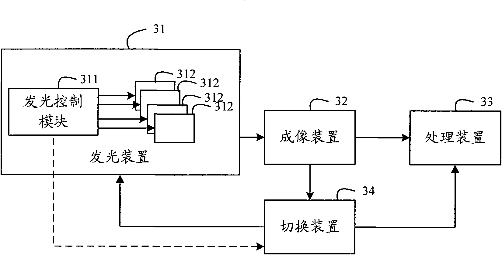
[0047] Embodiment 1: automatic switching mode.

[0048] image 3 It is a schematic structural diagram of the imaging system in Embodiment 1 of the present invention. Such as image 3 As shown, the system includes a light emitting device 31 , an imaging device 32 , a processing device 33 and a switching device 34 . The light emitting device 31 provides a light source. Preferably, the light emitting device 31 emits infrared light in order to make the emitted light source invisible to human eyes, thereby reducing interference to users. The imaging device 32 is movable and can be set in the operating handle, and the processing device 33 can be set in the operating handle, and can also be realized by a computer. The switching device 34 can be set in the light emitting device 31 , the imaging device 32 or the processing device 33 , or can be set separately.

[0049] Specifically, the lighting device 31 includes a lighting control module 311 and N lighting groups 312 , where N is...

Embodiment 2

[0074] Embodiment 2: manual switching mode.

[0075] Figure 9 It is a schematic structural diagram of the imaging system in Embodiment 2 of the present invention. Such as Figure 9 As shown, the system includes a light emitting device 91 , an imaging device 92 and a processing device 93 .

[0076] Wherein, the light emitting device 91 includes a light emitting control module 911 and N light emitting groups 912, where N is an integer greater than or equal to 2. Wherein, the light emitting group 912 is the same as the light emitting group 312 in the first embodiment.

[0077] The lighting control module 911 receives the lighting group information determined by the user according to the current moving range of the imaging device, and lights up the lighting group indicated by the received lighting group information. The lighting control module 911 may be implemented by using a mechanical switch or an electronic switch.

[0078] The imaging device 92 is configured to acquire ...


PUM


Abstract

The invention discloses an imaging system and a method for expanding the mobile range of an imaging device; the system is provided with at least two light-emitting groups; each light-emitting point group comprises two light-emitting points; all the light-emitting points are arranged on a fixing plane; only one light-emitting group is lighted up at the same moment; and the actual space between two light-emitting points in different light-emitting groups is different. When in use, according to the current mobile range of the imaging device, the current light-emitting group is determined and lightened. And then the actual space between two light-emitting points in the current light-emitting group is required to be adopted to replace corresponding parameters in the posture calculation formula of the imaging device, and the formula after replacement is adopted to calculate the posture information of the imaging device. By using the invention, the mobile range of the imaging device can be expanded without the increase of the perspective of the imaging device.

Description

technical field [0001] The invention relates to posture detection technology based on imaging images, in particular to an imaging system and method for expanding the movable range of an imaging device. Background technique [0002] At present, many game devices use infrared imaging devices to detect the attitude of the game handle. Such as figure 1 As shown, the operator is holding two operating handles, and the side with the imaging device on each operating handle is directed to the display. Two light emitting diodes (LEDs, light emitting diodes) are arranged on the display, which are respectively referred to as point A and point B, and LEDs emitting infrared light are usually used. The imaging device acquires an infrared light image from the light emitting device, and the infrared light image includes two high-brightness points. The processing device recognizes the two high-brightness points as point A and point B, and substitutes information such as the actual distance...

Claims


Application Information

Patent Timeline
IPC IPC(8): A63F13/10A63F13/40
Inventor 邓自军闫欢马韩俊刘振雷
Owner SUNPLUS TECH CO LTD
Why Eureka
Try Eureka