Mechanical power trolley

A mechanical and trolley technology, which is applied in the field of mechanical power-assisted devices and mechanical power-assisted trolleys, can solve laborious and other problems, achieve the effects of reducing labor intensity, improving power-assisted functions, and simple energy storage structure

Inactive Publication Date: 2009-10-21
SHANGHAI YANAN HIGH SCHOOL
View PDF0 Cites 0 Cited by
  • Summary
  • Abstract
  • Description
  • Claims
  • Application Information

AI Technical Summary

Problems solved by technology

[0004] The purpose of the present invention is to provide a mechanical power-assisted trolley, which is safe, reliable, easy to use, can improve the function of the existing trolley, and effectively overcome the laborious defect of the current trolley when carrying and transporting

Method used


Image

  • Mechanical power trolley

Examples


Embodiment Construction

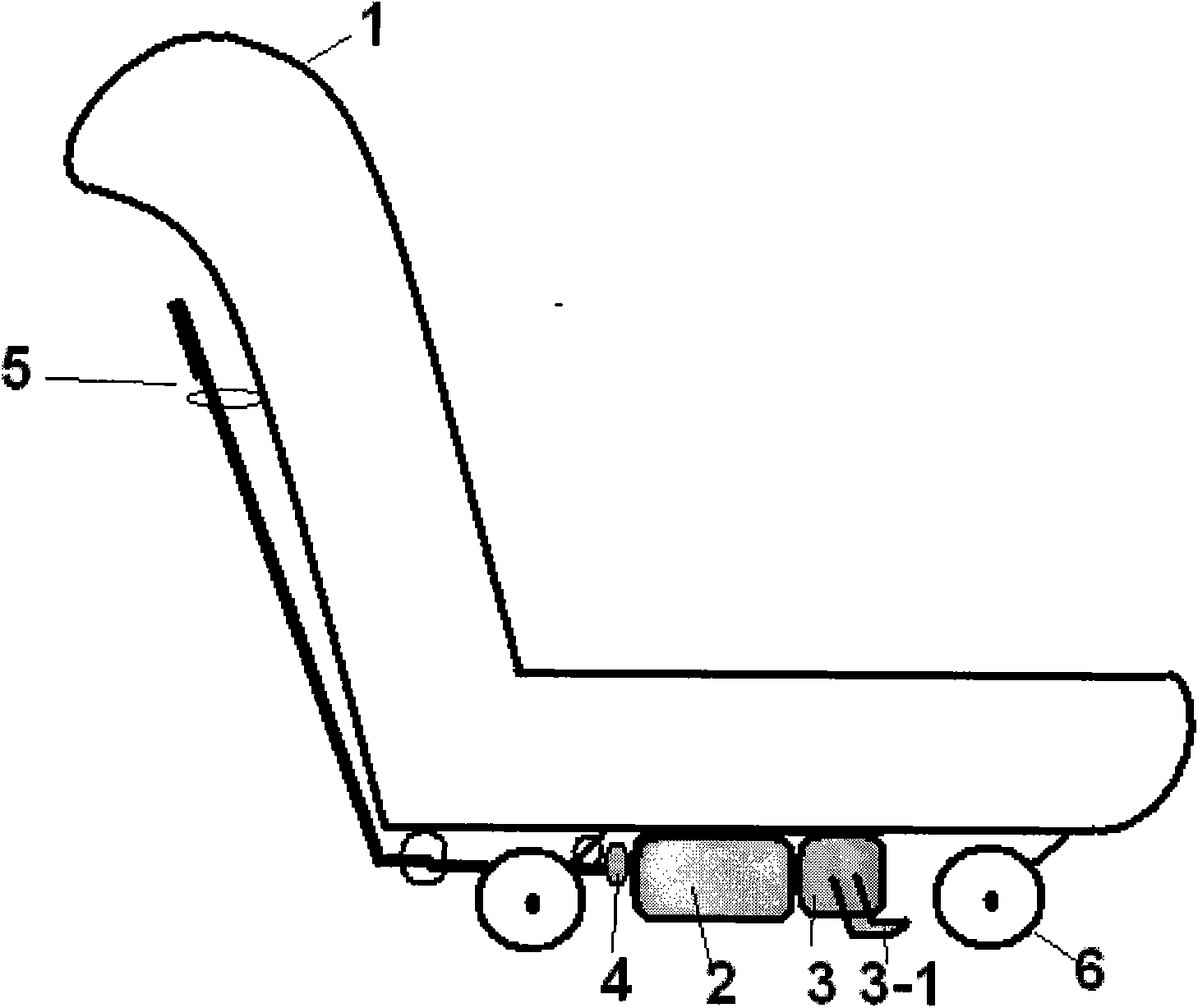
[0016] like figure 1 As shown, it is a schematic diagram of a mechanical power-assisted trolley of the present invention. It includes: a mechanical energy storage device 2, which is installed at the bottom of the trolley to store energy; an energy input structure 3, which is installed at the bottom of the trolley, and transmits external force to the mechanical energy storage device; A pedal input structure 3-1, which forms a complete external force input structure with the energy input structure 3; a clutch 4, which organically connects the mechanical energy storage device 2 with the wheels 6; a clutch lever 5, which will operate the clutch 4 Make the mechanical energy storage device 2 and the clutch of the wheel 6.

[0017] Those of ordinary skill in the art should recognize that the above embodiments are only used to illustrate the present invention, rather than as a limitation to the present invention, as long as within the scope of the spirit of the present invention, the...


PUM


Abstract

The invention discloses a mechanical power trolley. The mechanical power trolley is characterized by comprising a mechanical energy storage device which is arranged on the trolley and stores energy input by an energy input mechanism; the energy input mechanism which is arranged on the trolley and allows the input energy to drive the mechanical energy storage device to work through a mechanical structure; and a clutch which is arranged on the trolley and organically playing connection and disconnection action on the mechanical energy storage device and a wheel structure of the trolley, thus the mechanical power trolley having better practical and popularization significance.

Description

technical field [0001] The invention relates to a mechanical power-assisted trolley, in particular to a mechanical power-assisted device for the trolley, belonging to the technical field of mechanical power-assisted devices. Background technique [0002] Trolleys are widely used in society, especially for short-distance transportation of small batches of parts in the factory production process. Due to the unevenness of the road and the increase in the weight of parts, it is laborious to carry the trolley. [0003] Chinese Publication No. CN1389370, application date is January 8, 2003, and the invention titled "energy storage booster" relates to a device for storing the inertial energy generated when a bicycle is running or going downhill with a scroll spring. The device comprises a main shaft (there are three steel plates in the middle of the connecting shaft), a casing, a clutch, two gears on the left, three gears on the right (or three bevel gears), a top hook, a scroll sp...

Claims


Application Information

Patent Timeline
Patent Type & Authority Applications(China)
IPC IPC(8): B62B11/00
Inventor 朱守晨
Owner SHANGHAI YANAN HIGH SCHOOL
Why Eureka
Try Eureka