Rotor wiring fixing plate device

A technology of fixing board and terminal board, which is applied in the direction of electromechanical devices, manufacturing motor generators, electrical components, etc., can solve the problems of low reliability, can not maintain balance, etc., achieve high reliability, simple wiring of lead wires, and terminal board solid effect

Inactive Publication Date: 2012-09-19
无锡市宏泰电机股份有限公司
View PDF2 Cites 0 Cited by
  • Summary
  • Abstract
  • Description
  • Claims
  • Application Information

AI Technical Summary

Problems solved by technology

However, the rotors of similar wind turbines cannot maintain strict balance during rotation, and the rotor terminal board is usually thrown off due to excessive centrifugal force, resulting in low reliability during operation

Method used


Image

  • Rotor wiring fixing plate device
  • Rotor wiring fixing plate device
  • Rotor wiring fixing plate device

Examples


Embodiment Construction

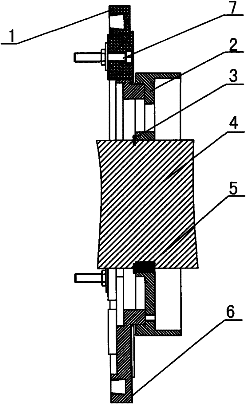
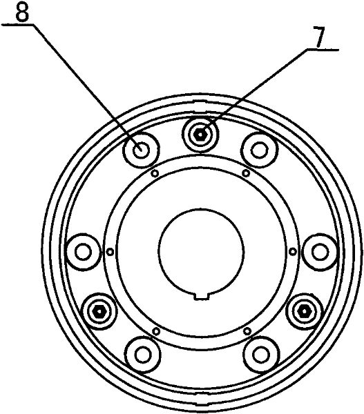
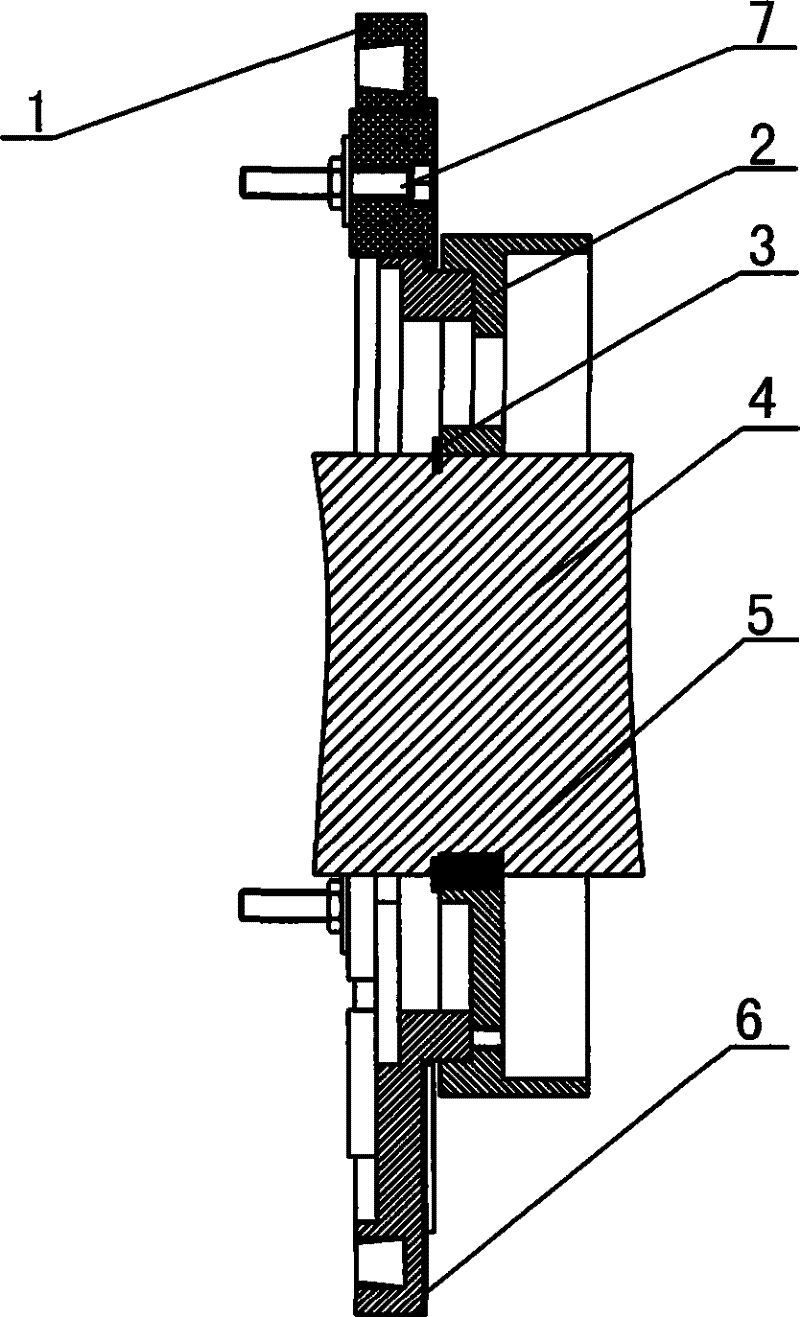
[0012] Such as Figure 1-2 As shown, the rotor wiring fixing plate device according to the present invention includes a balance ring 1, a rotor support plate 2, and a shaft 4. The end of the balance ring 1 is installed with an insulating partition 6, and the three insulating fixing blocks 8 pass through The insulating partition 6 is fixed in the balance ring 1, and the connecting bolt 7 passes through three insulating fixing blocks 8 and is fixed as a connecting post by nuts, and the winding lead wire is connected to the connecting post after passing through the other six insulating fixing blocks 8; The periphery of the shaft 4 is provided with a rotor support disc 2, and the side of the shaft 4 is provided with a circlip 3 and a key 5. The balance ring 1 is installed on the rotor support disc 2 of the shaft 4 to be assembled into a rotor terminal board. Through the improvement of the structure of the fixed plate device, the rotor can easily find a balance during operation; th...


PUM


Abstract

The invention discloses a rotor wiring fixing plate device, which comprises a balancing ring, a rotor supporting disk and a shaft. The end of the balancing ring is provided with an insulating partition by which three insulating fixed blocks are fixed in the balancing ring. Wiring bolts pass through the three insulating fixed blocks and are used as wiring terminals by nuts; the periphery of the shaft is provided with the rotor supporting disk and the side surface of the shaft is provided with an elastic retaining ring and a key; and the balancing ring is arranged on the rotor supporting disk ofthe shaft and assembled to a rotor wiring board. The rotor wiring fixing plate device has the advantages that: with the improvement of the structure of the fixed retaining plate device, a rotor can be easily balanced when in operation; the wiring board of the rotor is firm and can not be shaken off due to an excessive centrifugal force; and the outgoing line of a slip ring of the rotor has simplewiring and high reliability.

Description

technical field [0001] The invention relates to a device for a wind power generator, in particular to a rotor connection fixing plate device. Background technique [0002] Existing generators generally use the characteristic of electromagnetic induction to generate voltage, that is, charge difference. Some of the simplest generators consist of a magnet and a conductor, usually a coil. Inside the generator, the shaft is connected to a permanent magnet wound around the coil; When relative rotation occurs between the conductors, a voltage is induced in the conductors, and when the rotor rotates the shaft, which in turn rotates the magnet parts, a voltage is generated in the coils; the rotor blades act as barriers to the wind in the simplest way, when When the wind moves the blades, it transfers some of the energy to the rotor, which turns the shaft. However, the rotors of similar wind turbines cannot maintain strict balance during rotation, and the rotor terminal board is usu...

Claims


Application Information

Patent Timeline
Patent Type & Authority Patents(China)
IPC IPC(8): H02K15/00
Inventor 魏秋湘
Owner 无锡市宏泰电机股份有限公司
Why Eureka
Try Eureka