
Actuator

An actuator and action technology, applied in the direction of instruments, machines/engines, generators/motors, etc., can solve the problems such as the inability to fully correspond to the miniaturization and thinning of carrying, and achieve the improvement of life and energy efficiency, miniaturization, The effect of small energy loss

Inactive Publication Date: 2009-10-21
АДАМАНТ НАМИКИ ПРЕСИЖН ДЖУЭЛ КО ЛТД +1
View PDF2 Cites 2 Cited by
  • Summary
  • Abstract
  • Description
  • Claims
  • Application Information

AI Technical Summary

Problems solved by technology

[0010] However, the actuators disclosed in Patent Documents 1 and 2 have the following problems due to structural restrictions: in order to sufficiently ensure the moving distance of the lens, the device thickness (actuator height) in the moving direction of the lens is increased, thereby Cannot fully respond to the miniaturization and thinning required by the lens moving mechanism for portable terminals

Method used


Image

  • Actuator
  • Actuator
  • Actuator

Examples


Embodiment Construction

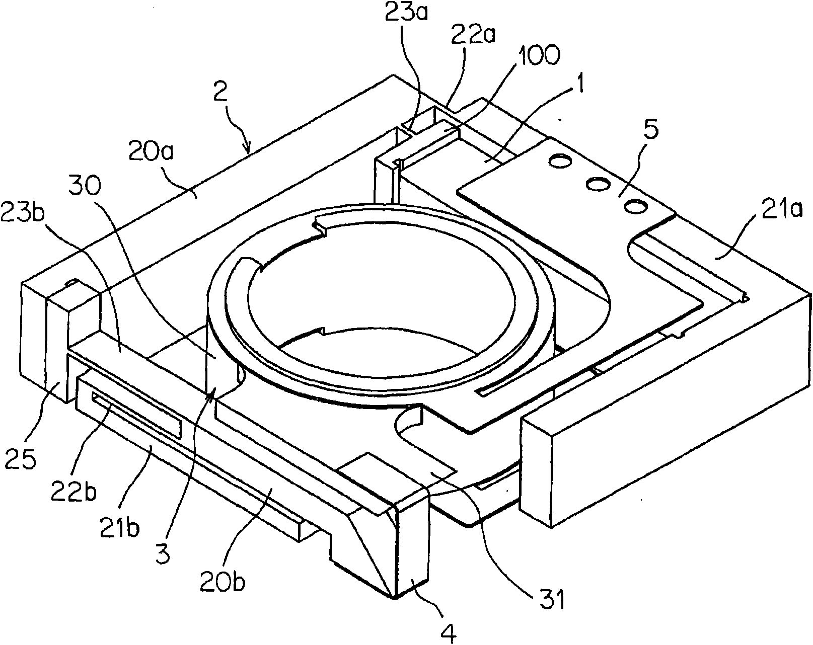
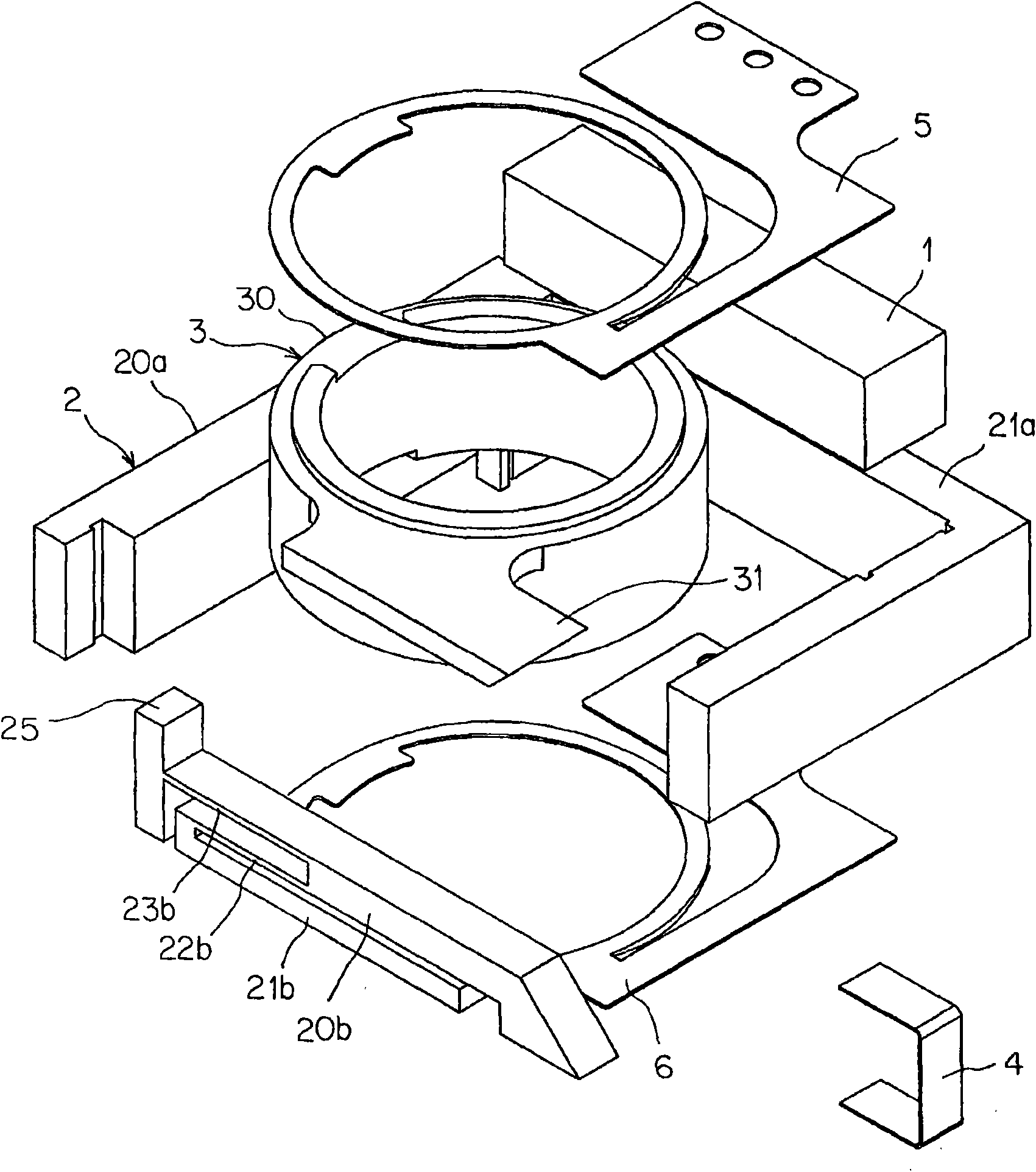
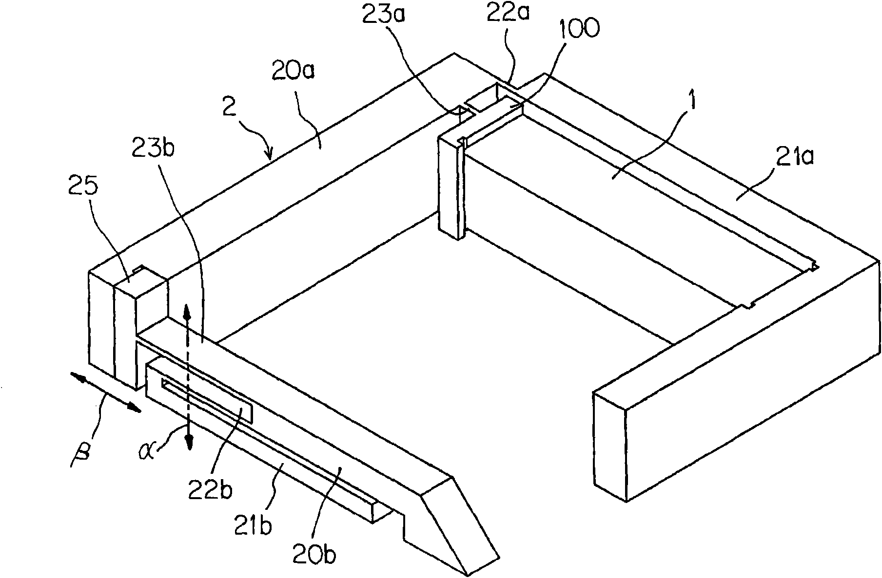
[0098] Figure 1 to Figure 5 One embodiment of the actuator of the present invention is shown, and a case where it is applied to a lens actuator incorporated in a lens module of a portable terminal is shown. figure 1 For the overall stereogram, figure 2 For the exploded stereogram, image 3 It is a perspective view showing a state in which movable parts are removed, Figure 4 For its top view, Figure 5 It is an explanatory diagram showing the function (operation method). In the figure, 3 is a movable member that is displaced by an actuator, which is a lens holder in this embodiment.

[0099] The actuator includes: a drive member 1 that deforms with a deformation amount corresponding to input energy and outputs the deformation as a displacement in a uniaxial direction; and amplifies the displacement output from the drive member 1 while amplifying the displacement The displacement amplifying mechanism 2 is transmitted to the above-mentioned movable member 3 to displace th...


PUM


Abstract

Provided is an actuator which can be reduced in size and thickness while keeping the moving distance of a mechanical element or an optical element sufficient. The unidirectional displacement, as outputted from a drive member (1) such as a piezoelectric element, is transmitted, while being enlarged in displacement, to a movable member (3) by a displacement enlarging mechanism (2) of a specific constitution, which includes a plurality levers (20a and 20b) arranged along the displacement transmitting direction, stationary portions (21a and 21b) for supporting those levers (20a and 20b), fulcrum joint portions (22a and 22b) made elastically deformable for forming the fulcrums of the levers, and elastically deformable joint portions (23a and 23b) for establishing the points of force of the levers. Although the size and thickness are reduced, the actuator can retain a large extent of movement for the movable member (3).

Description

technical field [0001] The present invention relates to an actuator suitable as a drive mechanism for mechanical elements or optical elements of small precision equipment. Background technique [0002] A camera module incorporated into a portable terminal such as a mobile phone requires a high-speed and high-precision autofocus function or zoom function similarly to a general electronic camera (digital camera). [0003] In order to realize these functions, it is necessary to move the lens group of the camera module with high speed and high precision in the direction of the optical axis, and a mechanism and a driving mechanism for this are required. With the advancement of miniaturization, miniaturization and thinning of the above-mentioned camera module or its constituent parts are required. [0004] As an actuator for moving the lens of a camera module, an actuator provided with a screw-type rotating mechanism is generally known, but such a mechanism has a large energy los...

Claims


Application Information

Patent Timeline
IPC IPC(8): F03G7/06G02B7/04G02B7/08H02N2/00
Inventor 久乡智之古川武志矢野健徐世杰
Owner АДАМАНТ НАМИКИ ПРЕСИЖН ДЖУЭЛ КО ЛТД
Learn More