External gear shift for a manual transmission

A technology of shifting device and transmission, applied in transmission control, components with teeth, belt/chain/gear, etc., can solve the problem of laborious shifting process

Inactive Publication Date: 2009-10-28
GM GLOBAL TECH OPERATIONS LLC
View PDF5 Cites 5 Cited by
  • Summary
  • Abstract
  • Description
  • Claims
  • Application Information

AI Technical Summary

Problems solved by technology

This point is laborious for the driver in the shifting process with channel change, because the shift/gear lever cannot move continu

Method used


Image

  • External gear shift for a manual transmission
  • External gear shift for a manual transmission
  • External gear shift for a manual transmission

Examples


Embodiment Construction

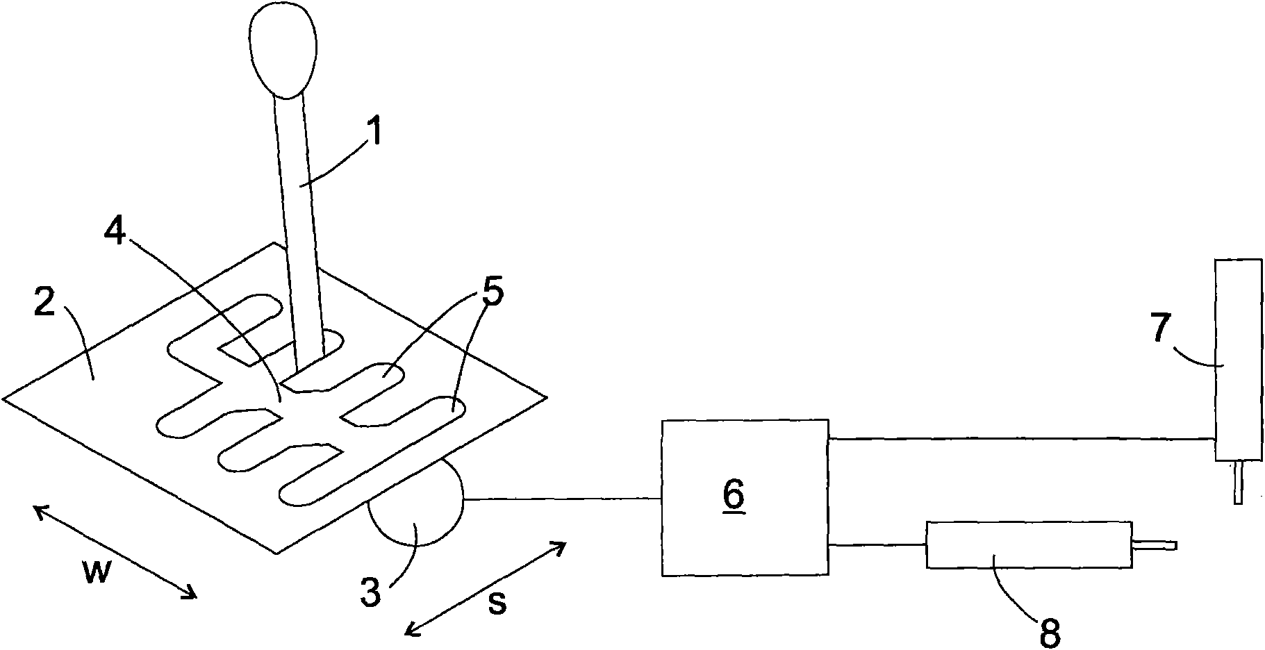
[0021] exist figure 1 The schematically shown shifting device comprises an external shifting device with a shift / gear lever 1 projecting into the vehicle cabin and guided in a gate plate 2 and a sensor 3 for detecting the position of the shift / gear lever 1 , the shift / gear lever can move in the direction of the selection channel 4 reserved in the chute plate 2 and the direction of the shift channel 5 intersecting with the selection channel 4 . The sensor 3 supplies the coordinate values ​​s, w of the selector lever 1 with respect to these two directions to the control circuit 6 . An actuator arrangement with two degrees of freedom, shown here as two single servo cylinders 7 , 8 , is connected to the control circuit 6 . The actuating cylinders 7 , 8 effect a shifting movement of a shifting shaft of a multi-stage transmission known per se, not shown, in two degrees of freedom, eg axial displacement and rotation.

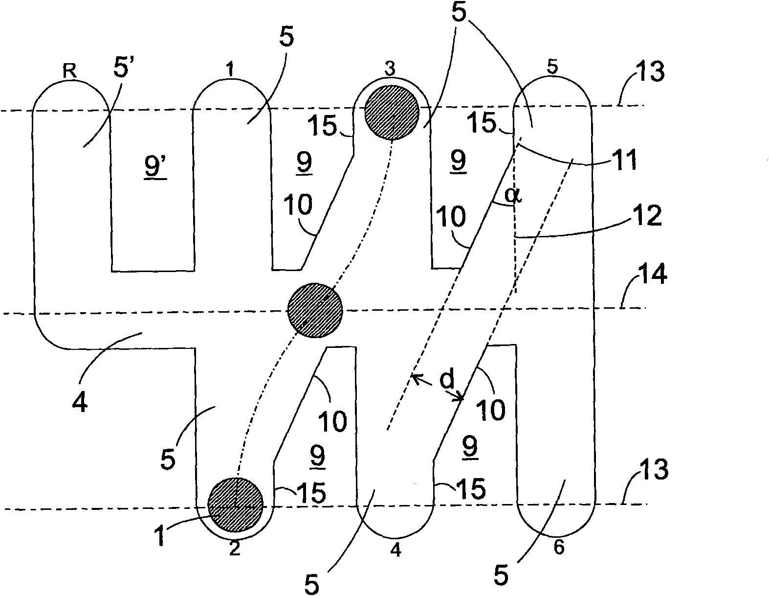
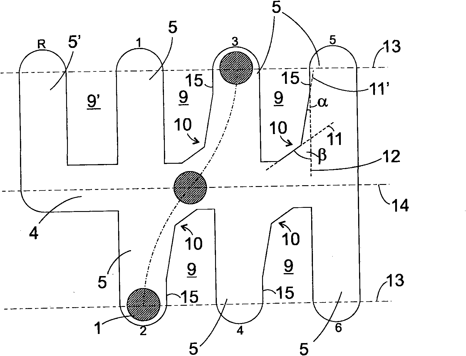
[0022] As long as the selector / gear lever 1 is in one of the ch...


PUM


Abstract

An external gear shift for the gear selection in a manual transmission is provided that includes, but is not limited to a gearshift/selector lever, which is guided in a link plate and which is movablealong a selector track and a plurality of shifting tracks, and a measuring sensor to detect an instantaneous position (s, w) of the gearshift/selector lever. Guide fingers of the link plate disposedbetween shifting and selector tracks each have flanks oriented obliquely to the shifting and selector tracks.

Description

technical field [0001] The invention relates to an external shifting device for selecting gears in a transmission, having a shift / gear lever and a sensor for detecting the position of the shift / gear lever. Such an external shifter typically forms the user interface of a shift-by-wire device, wherein a control circuit controls the actuators in dependence on the detected shift / gear lever position. Background technique [0002] Transmissions traditionally have shift shafts that can move in two degrees of freedom. By moving in one of these degrees of freedom, the selector shaft engages one or more synchronizers required to engage the gear, and by moving in the other degree of freedom, the selector shaft actuates the respective selected synchronizer adjustment movement. These movements have to take place essentially in succession, since the gearshift shaft has to engage before its adjusting movement can be driven. In order to support the driver when changing gears and to ensur...

Claims


Application Information

Patent Timeline
IPC IPC(8): F16H59/04
CPCF16H61/24F16H59/044F16H2061/242Y10T74/2014
Inventor 克里斯琴·鲁布萨姆简·斯波尔德
Owner GM GLOBAL TECH OPERATIONS LLC
Why Eureka
Try Eureka