
Light-emitting diode lamp

A technology of light-emitting diodes and lamps, which is applied to the semiconductor devices of light-emitting elements, light sources, electric light sources, etc., which can solve the problems of limited irradiation range and poor lighting effect, and achieve the effect of wide irradiation range

Inactive Publication Date: 2009-10-28
STATE GRID TIANJIN ELECTRIC POWER
View PDF0 Cites 4 Cited by
  • Summary
  • Abstract
  • Description
  • Claims
  • Application Information

AI Technical Summary

Problems solved by technology

Since the light-emitting diode is only installed on the plane on one side of the heat sink, the light emitted by it can only radiate outwards from the side plane of the heat sink at a small angle, the irradiation range is limited, and the lighting effect is not good.

Method used

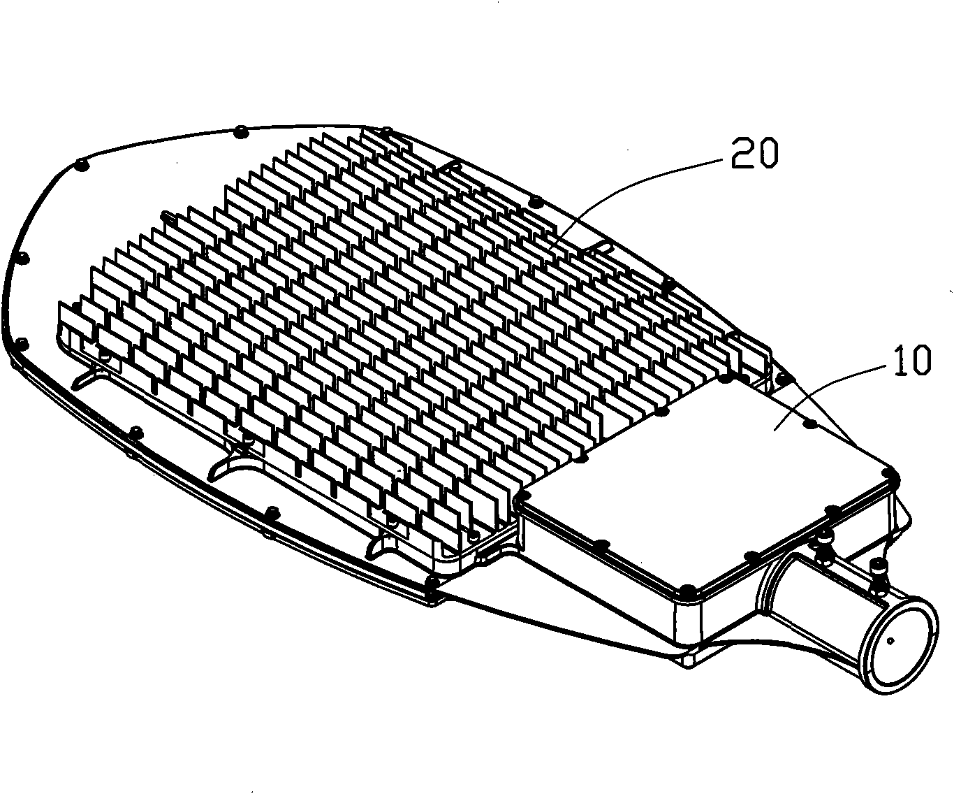

Image

  • Light-emitting diode lamp
  • Light-emitting diode lamp
  • Light-emitting diode lamp

Examples


Embodiment Construction

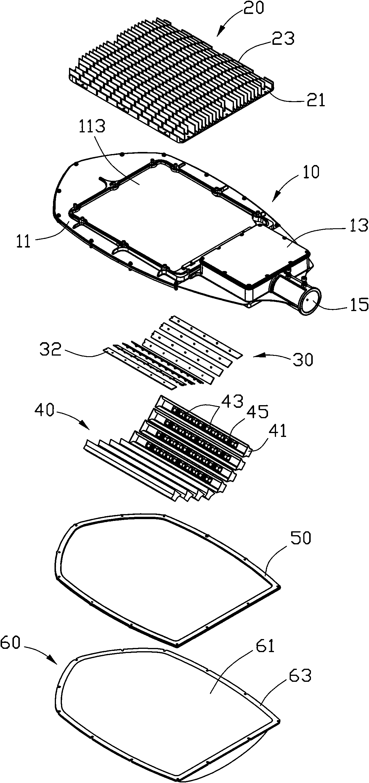
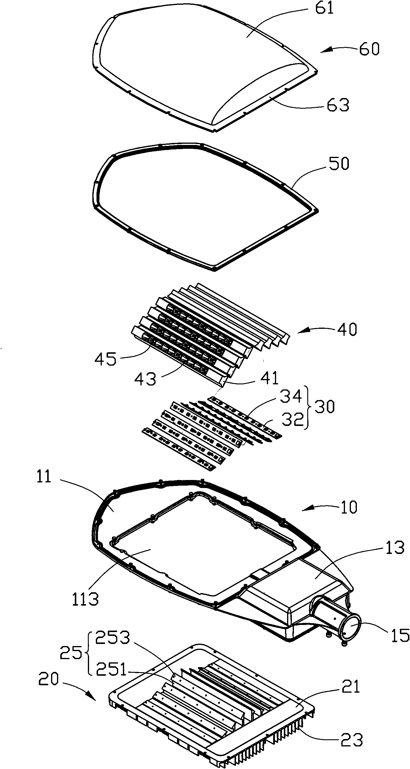
[0012] like figure 1 and figure 2 As shown, the light-emitting diode lamp of the present invention is roughly paddle-shaped, and includes a lamp frame 10, a heat sink 20 installed on one side of the light frame 10, a plurality of light-emitting diode modules 30 attached to the heat sink 20, and a cover device. Several reflectors 40 on the LED module 30 and a transparent lamp cover 60 installed on the other side of the lamp frame 10 .

[0013] Please also see image 3 The lamp holder 10 includes a fixing frame 11 , a driving circuit module 13 located at one end of the fixing frame 11 , and a lamp holder 15 arranged in the middle of one end of the driving circuit module 13 . The driving circuit module 13 is used to electrically connect with the LED module 30 . The lamp socket 15 is used for connecting with a lamp pole (not shown). The fixing frame 11 is roughly paddle-shaped, and a rectangular opening 113 is defined in the middle thereof, and a plurality of arc-shaped edges...


PUM


Abstract

The invention relates to a light-emitting diode lamp which comprises a lamp bracket and a plurality of light-emitting diode modules arranged on the lamp bracket, wherein the light-emitting diode modules are opposite pairwise and are arranged inclining to two opposite sides from the middle part of the lamp bracket at a certain angle, and angles between the opposite light-emitting diode modules gradually increase from the middle part of the lamp bracket to two opposite sides of the lamp bracket. Compared with the prior art, the light-emitting diode modules of the light-emitting diode lamp are pairwise opposite and are arranged inclining to two opposite sides from the middle part of the lamp bracket at a certain angle, and the angles between the opposite light-emitting diode modules gradually increase from the middle part of the lamp bracket to two opposite sides of the lamp bracket so as to lead light transmitted by the light-emitting diode modules to radiate towards the periphery of a radiator so that the irradiation range of the light-emitting diode is wider.

Description

technical field [0001] The invention relates to a lighting device, in particular to a light emitting diode lamp. Background technique [0002] As a high-efficiency light source, light-emitting diodes have many characteristics such as environmental protection, power saving, and long life, and have been widely used in various fields. [0003] A traditional LED lamp includes a flat radiator and several LED modules installed on one side of the radiator. When the light-emitting diode is turned on, the light-emitting diode module installed on one side of the radiator plays a lighting role. Since the light emitting diode is only installed on the plane of one side of the heat sink, the light emitted by it can only radiate outwards from the side plane of the heat sink at a small angle, so the irradiation range is limited and the lighting effect is not good. Contents of the invention [0004] In view of this, it is necessary to provide a light-emitting diode lamp with a larger irr...

Claims


Application Information

Patent Timeline
Patent Type & Authority Applications(China)
IPC IPC(8): F21V21/116F21V29/00F21Y101/02
CPCF21K9/00F21Y2105/001F21V29/004F21V29/2262F21S8/08F21V19/001F21V29/2243F21Y2101/02F21W2131/103F21S2/005F21S8/086Y10S362/80F21V29/75F21V29/76F21Y2105/10F21Y2115/10F21V29/763F21V29/89
Inventor 郑世崧王忠清刘宜三
Owner STATE GRID TIANJIN ELECTRIC POWER
Learn More