Ophthalmic Microscope and Functionality Enhancement Unit

a technology of functional enhancement and optical design, applied in the field of ophthalmologic microscopes, can solve the problems of complex optical design of ophthalmologic microscopes, and achieve the effects of increasing the degree of freedom in optical design, and facilitating the addition of functions of oct to ophthalmologic microscopes

Active Publication Date: 2020-07-09
KK TOPCON
View PDF0 Cites 3 Cited by
  • Summary
  • Abstract
  • Description
  • Claims
  • Application Information

AI Technical Summary

Benefits of technology

[0069]In the ophthalmologic microscope of the first invention, the optical axis of the observation optical system penetrates through the objective lens while the optical axis of the OCT optical system penetrates through the objective lens for OCT which has been provided aside from the objective lens. With this configuration, the ophthalmologic microscope of the present invention is one which the observation optical system and the OCT optical system are independent from one another. Therefore, the ophthalmologic microscope of the present invention can perform optical design without the observation optical system and the OCT optical system being influenced each other and thus it is effective in increasing the degree of freedom in the optical design. The ophthalmologic microscope of the present invention is also effective in being able to scan the measuring light in a wide irradiation range even with an objective lens for OCT of small aperture because the deflection optical element for scanning of the OCT optical system and the objective lens for OCT are in a substantially optically conjugate positional relation.
[0070]For the function expansion unit of the second invention and the function expansion set of the third invention, the optical axis of the observation optical system for the ophthalmologic microscope penetrates through the objective lens while the optical axis of the OCT optical system for the function expansion unit does not penetrate through the objective lens but penetrates through the objective lens for OCT. With this configuration, the OCT optical system for the function expansion unit is independent from the observation optical system for the ophthalmologic microscope, thereby allows for unitization and is also effective in increasing the degree of freedom in the optical design. As the function expansion unit is attachable to and detachable from the ophthalmologic microscope via a joint, the function expansion unit and the function expansion set of the present invention are effective in readily adding functions of OCT to the ophthalmologic microscope. Also, the function expansion unit and the function expansion set of the present invention is effective in being able to scan the measuring light in a wide irradiation range even with an objective lens for OCT of small aperture because the deflection optical element for scanning of the OCT optical system and the objective lens for OCT are in a substantially optically conjugate positional relation.

Problems solved by technology

However, the Greenough ophthalmologic microscope requires a complex optical design in order to incline the left and right observation optical systems each other to set the stereo angle.

Method used


Image

  • Ophthalmic Microscope and Functionality Enhancement Unit
  • Ophthalmic Microscope and Functionality Enhancement Unit
  • Ophthalmic Microscope and Functionality Enhancement Unit

Examples


first embodiment

1-2. First Embodiment

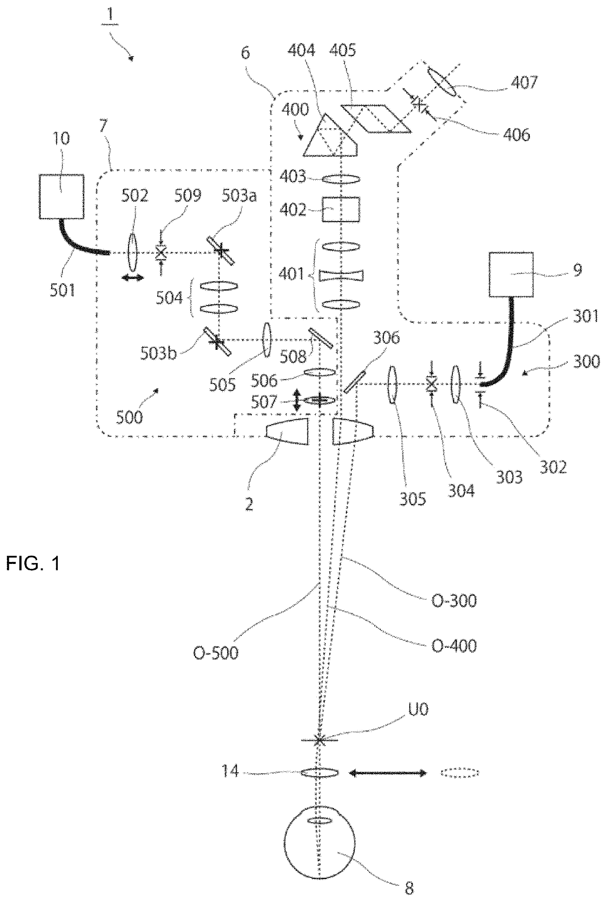
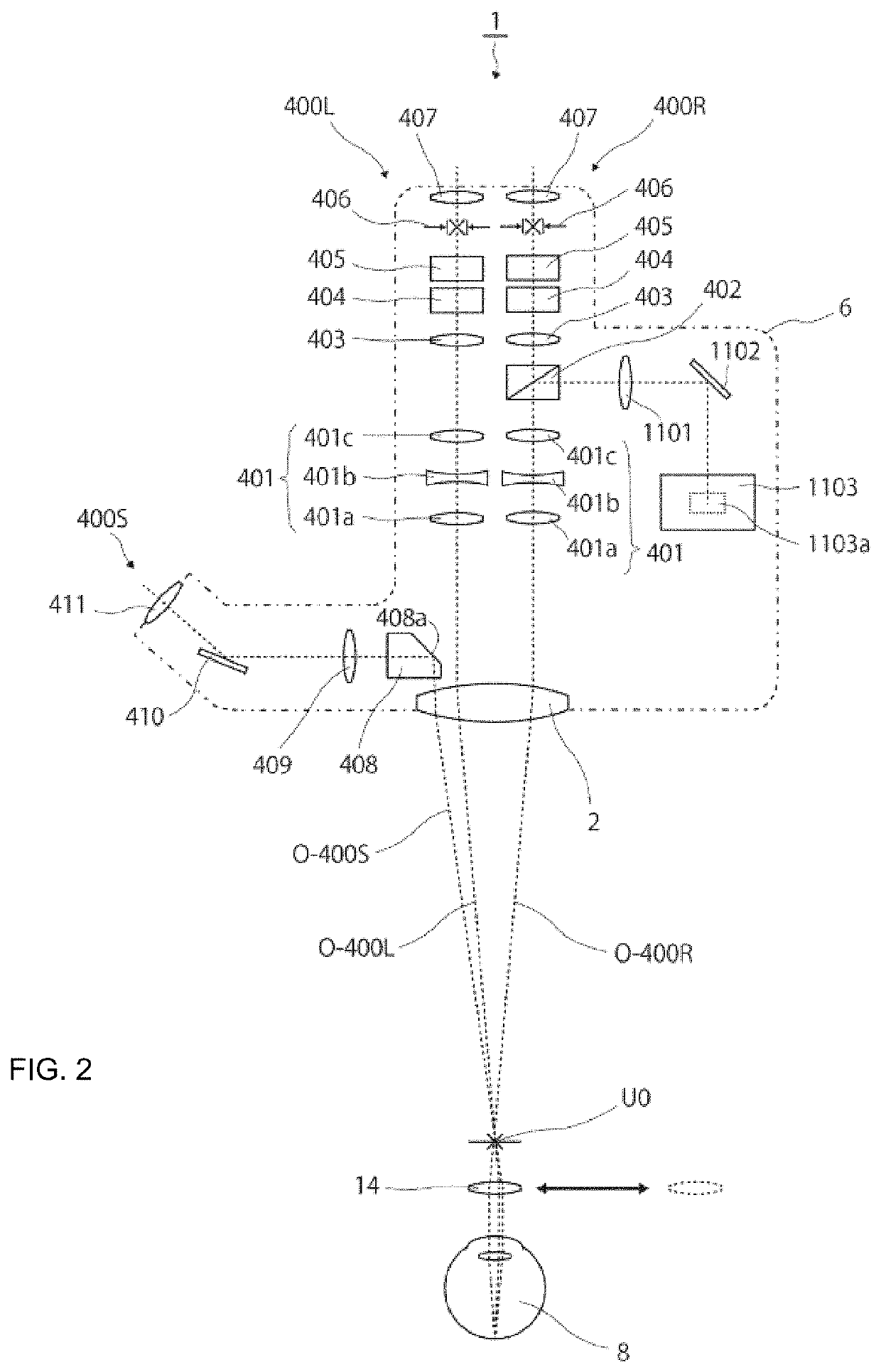
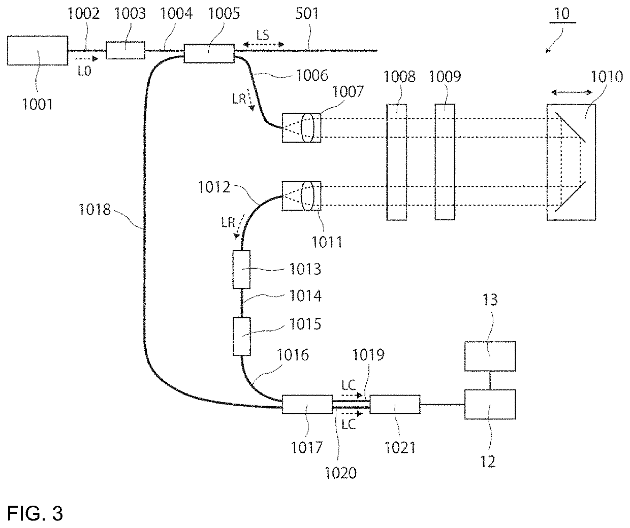
[0109]Hereinafter, examples of the embodiments of the present invention will be fully described in reference to drawings. FIGS. 1-4 schematically illustrate the first embodiment which is an example of the ophthalmologic microscope of the present invention. FIG. 1 is a schematic diagram from a side view of the configuration of an optical system for the ophthalmologic microscope of the first embodiment, and FIG. 2 is a schematic diagram from a front view. Also, FIG. 3 schematically illustrates the optical configuration of an OCT unit, and FIG. 4 schematically illustrates a shape of objective lens.

[0110]As shown in FIG. 1, the optical system of the ophthalmologic microscope 1 comprises an objective lens 2, an illuminating optical system 300, an observation optical system 400, and an OCT optical system 500.

[0111]The objective lens 2, the illuminating optical system 300, and the observation optical system 400 are accommodated in an ophthalmologic microscope body 6. O...

second embodiment

1-4. Second Embodiment

[0186]Preferably, the OCT optical system can be additionally incorporated as an extension function into the ophthalmologic microscope comprising an observation optical system and an illuminating optical system. To additionally incorporate in this way, the inventors found that it can be compactly incorporated by bending the light path of the OCT optical system twice to adapt to the original function of the microscope.

[0187]That is, in the ophthalmologic microscope of the present invention, it is preferable that the OCT optical system comprises:

[0188]a first optical member that guides a light from an OCT light source to a first optical axis direction;

[0189]a first reflecting member that guides the light guided to the first optical axis direction to a second optical axis direction substantially perpendicular to the first optical axis direction;

[0190]a second optical member that relays the light guided to the second optical axis direction; and

[0191]a second reflect...

third embodiment

1-5. Third embodiment

[0223]A shape of an objective lens used in the third embodiment which is other example of the ophthalmologic microscope of the present invention is shown in FIG. 11. FIG. 11 (A) illustrates an objective lens seen from the optical axis direction and FIG. 11 (B) is a cross-sectional view in the plane including a line AA′ of FIG. 11 (A).

[0224]As shown in FIG. 11 (A), the objective lens 2 used in the third embodiment has a shape of circular lens with a partial cutout. And, the light path of the OCT optical system P-500 passes through that cutout portion.

[0225]Also, as shown in FIG. 11 (B), the sectional shape of the objective lens 2 has a partial shape of convex lens which has been partially cut away.


PUM


Abstract

The object of the present invention is to develop an ophthalmologic microscope of a new method that increases the degree of freedom in the optical design in the Galilean ophthalmologic microscope provided with an OCT optical system. The present invention provides an ophthalmologic microscope 1 comprising; an illuminating optical system 300, an observation optical system 400; an objective lens 2; and an OCT optical system 500, characterized in that the optical axis 0-500 of the OCT optical system does not penetrate through the objective lens 2, it comprises objective lens for OCT 507 through which the optical axis 0-500 of the OCT optical system penetrates, and deflection optical elements 503a, 503b for scanning of the OCT optical system and the objective lens for OCT 507 are in a substantially optically conjugate positional relation.

Description

RELATED APPLICATIONS[0001]The present U.S. patent application is U.S. National Phase Application under 35 U.S.C. 371 of International Application No. PCT / JP2018 / 017568 filed on May 2, 2018. This application claims priority under the Paris Convention to Japanese Patent Application Nos. 2017-091997 filed May 2, 2017, 2017-165187 filed Aug. 30, 2017, and 2018-056763 filed Mar. 23, 2018, the entire disclosures of which are incorporated herein by reference in their entireties.TECHNICAL FIELD[0002]The present invention relates to an ophthalmologic microscope comprising an illuminating optical system for illuminating a subject's eye and an observation optical system for observing the subject's eye, such as a fundus camera, a slit lamp, a microscope for ophthalmic surgery. The inventive ophthalmologic microscope is characterized in that it comprises an OCT optical system capable of obtaining tomographic images of the subject's eye with Optical Coherence Tomography (abbreviated as OCT) and t...

Claims


Application Information

Patent Timeline
Patent Type & Authority Applications(United States)
IPC IPC(8): A61B3/10A61B3/13
CPCA61B3/132A61B3/102A61B3/13
Inventor FUKUMA, YASUFUMIOOMORI, KAZUHIRO
Owner KK TOPCON
Why Eureka
Try Eureka