
Illumination-bias light-emitting diode (LED) lamp

A technology of LED lamps and LED lighting, which is applied to the components of lighting devices, lighting devices, lighting and heating equipment, etc., and can solve the problems of restricting the promotion and use of LED lamp technology, low utilization rate of light energy, and short development time , to achieve the effect of easy promotion and use, high light energy utilization rate and good lighting effect

Inactive Publication Date: 2013-06-05
XIAN JINNUO PHOTOELECTRIC TECH
View PDF0 Cites 3 Cited by
  • Summary
  • Abstract
  • Description
  • Claims
  • Application Information

AI Technical Summary

Problems solved by technology

[0002] With the development of science and technology, LED lighting technology using semiconductor light is becoming more and more mature. Because of its energy saving, shock resistance, moisture resistance and long service life, it has gradually replaced traditional lighting in various types of lighting. It has been popularized in various fields of lighting, but due to various reasons such as short development time and immature technology, traditional LED lamps have been greatly restricted in terms of light energy utilization rate and beam irradiation range. LED lighting fixtures still have defects and deficiencies such as small illumination range, concentrated illumination, and low light energy utilization rate, which greatly restricts the promotion and use of LED lighting technology.

Method used


Image

  • Illumination-bias light-emitting diode (LED) lamp
  • Illumination-bias light-emitting diode (LED) lamp

Examples


Embodiment Construction

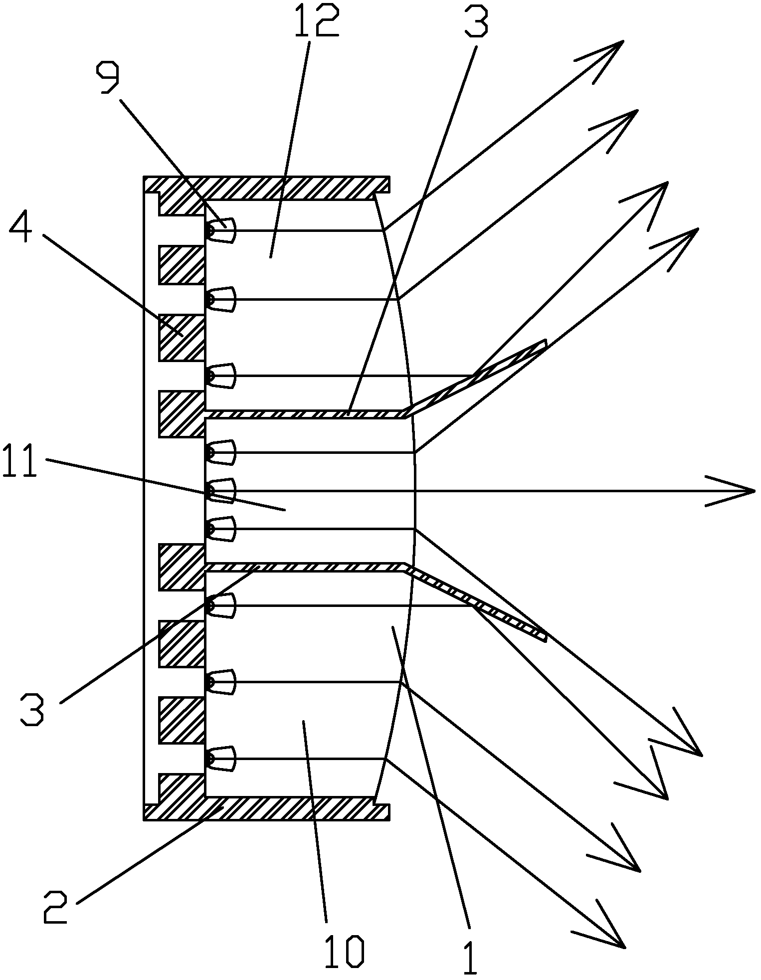
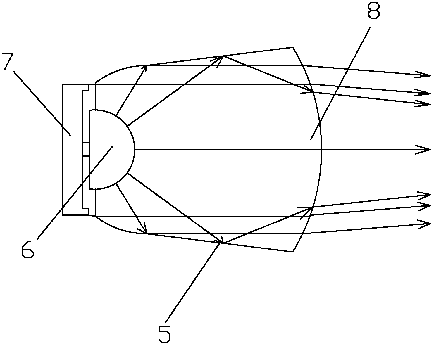
[0026] Such as figure 1 with figure 2 As shown, the present invention includes a lampshade 2, a lamp holder 4 installed on the inner wall of one side of the lampshade 2 and a diverging lens 1 installed on the other side of the lampshade 2, and the space surrounded by the lampshade 2 and the diverging lens 1 is provided with Two double-sided reflectors 3 for dividing the space enclosed by the lampshade 2 and the diverging lens 1 into three lighting areas, each of which is uniformly provided with a plurality of LED lighting units 9; the LED lighting The unit 9 includes a light source base 7, an LED light source 6 installed on the light source base 7, and a condenser cover 5 fixedly connected to the light source base 7 at one end and covered on the LED light source 6, and the other end of the condenser cover 5 is installed There are 8 condenser lenses.

[0027] Such as figure 1 with figure 2 As shown, in this embodiment, three LED lighting units 9 are uniformly arranged in ...


PUM


Abstract

The invention discloses an illumination-bias light-emitting diode (LED) lamp which comprises a lamp shade, a lamp socket mounted on one side of the lamp shade and a divergent lens mounted on the other side of the lamp shade. Two double-faced reflectors are arranged in a space surrounded by the lamp shade and the divergent lens to divide the space surrounded by the lamp shade and the divergent lens into three illumination areas, and a plurality of LED illumination units are evenly arranged in each illumination area. Each LED illumination unit comprises a light source base, an LED light source mounted on the light source base and a light-gathering shade, wherein the light-gathering shade covers the LED light source, one end of the light-gathering shade is fixedly connected with the light source base, and a condensing lens is mounted at the other end of the light-gathering shade. The illumination-bias LED lamp is simple in structure, reasonable in design, convenient to manufacture, low in realization cost, convenient and fast to operate and use, high in light efficiency, uniform in illumination, large in illumination range, saving in energy, good in luminous effect, strong in practical applicability and easy to popularize.

Description

technical field [0001] The invention relates to the technical field of LED lighting, in particular to an LED lamp for partial lighting. Background technique [0002] With the development of science and technology, LED lighting technology using semiconductor light is becoming more and more mature. Because of its energy saving, shock resistance, moisture resistance and long service life, it has gradually replaced traditional lighting in various types of lighting. It has been popularized in various fields of lighting, but due to various reasons such as short development time and immature technology, traditional LED lamps have been greatly restricted in terms of light energy utilization rate and beam irradiation range. LED lighting fixtures in China still have defects and deficiencies such as small illumination range, concentrated illumination, and low light energy utilization rate, which greatly restricts the promotion and use of LED lighting technology. Contents of the inven...

Claims


Application Information

Patent Timeline
Patent Type & Authority Applications(China)
IPC IPC(8): F21S2/00F21V13/04F21Y101/02F21K9/00F21Y115/10
Inventor 胡焕性李文辉王琦
Owner XIAN JINNUO PHOTOELECTRIC TECH
Learn More