Photocatalytic sterilization and disinfection device

A sterilization and disinfection device, photocatalytic technology, applied in the direction of sterilization/microdynamic water/sewage treatment, illumination water/sewage treatment, etc., can solve the problems of unable to use sunlight, single purification function, poor purification effect, etc. Good disinfection effect, wide irradiation range and good purification effect

Active Publication Date: 2021-10-22
ZHENGZHOU UNIVERSITY OF LIGHT INDUSTRY
View PDF10 Cites 3 Cited by
  • Summary
  • Abstract
  • Description
  • Claims
  • Application Information

AI Technical Summary

Problems solved by technology

[0005] 1. The above-mentioned patent needs to install an ultraviolet lamp inside the device, which cannot use sunlight to directly react with the titanium dioxide photocatalytic coating, and the cost is high. At the same time, it is necessary to control the ultraviolet lamp in real time during use, which is troublesome;
[0006] 2. The purification effect of the above patents is poor, and the hydroxyl radicals produced by the reaction between the ultraviolet lamp and the titanium dioxide photocatalytic coating cannot fully react with the water body;
[0007] 3. The purification function of the above-mentioned patents is relatively simple, and the water body can only be purified by the reaction of the ultraviolet lamp and the titanium dioxide photocatalytic coating, and it is impossible to make the silica powder and the water body form a suspension system at the same time;

Method used


Image

  • Photocatalytic sterilization and disinfection device
  • Photocatalytic sterilization and disinfection device
  • Photocatalytic sterilization and disinfection device

Examples


Embodiment 1

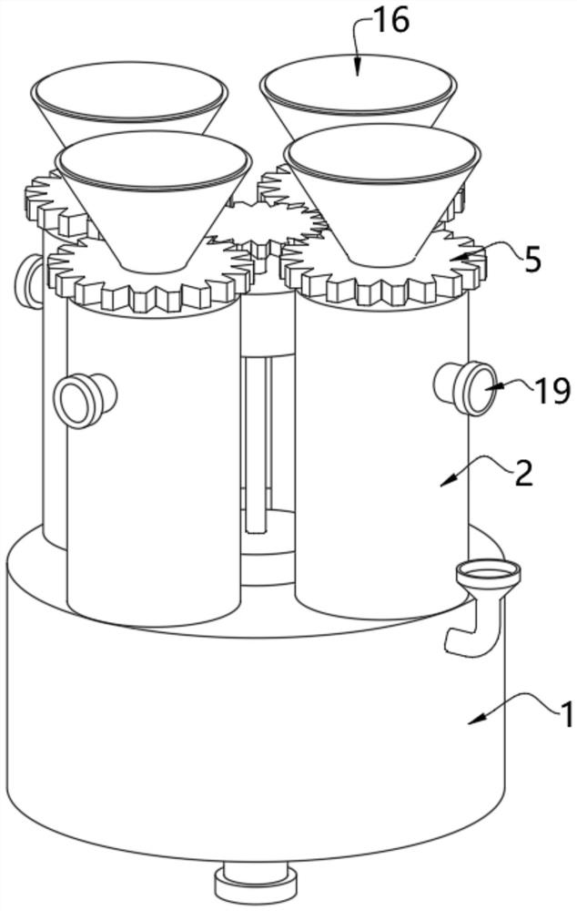
[0048] see Figure 1-5 , photocatalytic sterilization and disinfection device, including

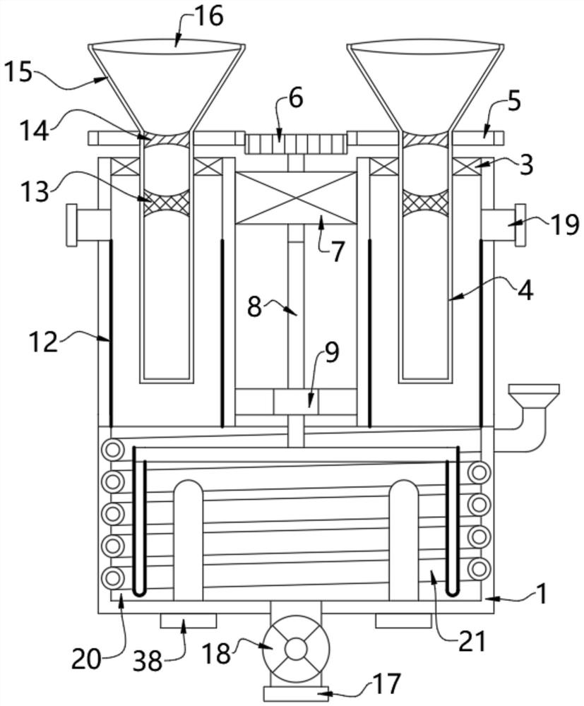
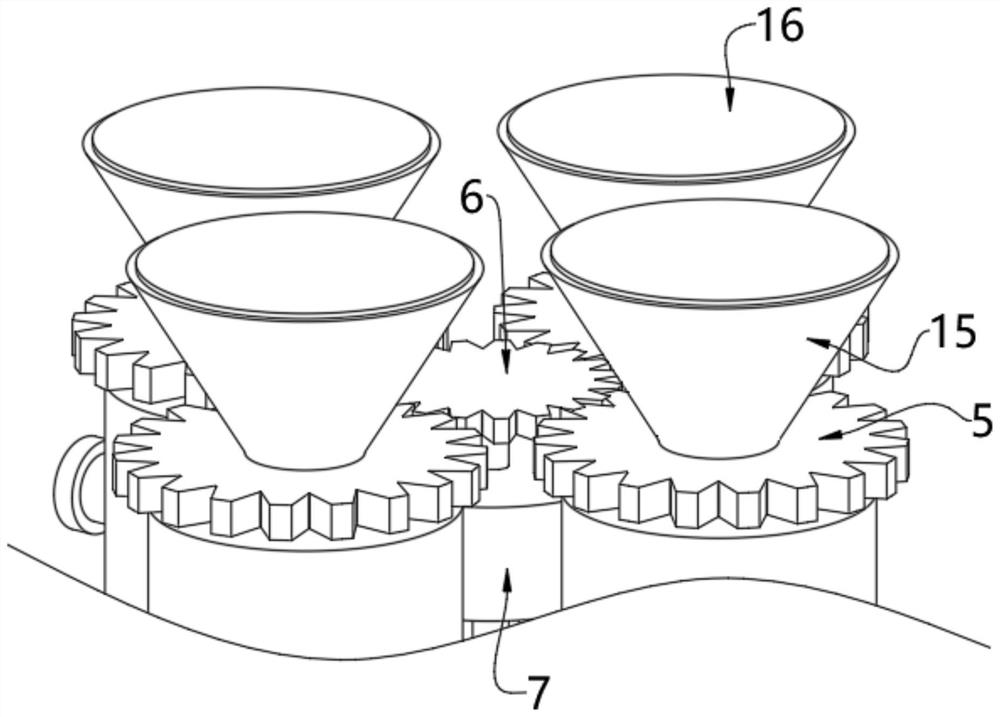
[0049] Bottom cylinder 1, a water inlet pipe 17 is fixedly installed at the center of the bottom of the bottom cylinder 1, a control valve 18 is arranged inside the water inlet pipe 17, an inner cavity 20 is formed inside the bottom cylinder 1, and the edge of the top of the bottom cylinder 1 is evenly fixed Several top cylinders 2 are installed, bearings 3 are fixedly installed on the tops of the inner walls of several top cylinders 2, quartz sleeves 4 are fixedly installed on the inner walls of the bearings 3, double-headed motors 7 are fixedly installed on the outer wall of the top cylinder 2, double-headed The motor 7 can be selected as the 50S90-5-11 model of the Beili brand, and the driving device connected between the double-head motor 7 and the quartz sleeve 4 is used to drive the rotation of the quartz sleeve 4;

[0050] The outer wall of the top tube 2 is fixedly installed wit...

Embodiment 2

[0055] see figure 2 , Figure 4 with Image 6 , on the basis of Embodiment 1, a stirring rod 11 is rotated at the edge of the inner cavity 20, the outer wall of the stirring rod 11 is coated with a titanium dioxide photocatalytic coating 12, and the inner cavity 20 is uniformly provided with an ultraviolet lamp 38, The linkage device connected to the double-head motor 7 and the stirring rod 11 is used to drive the stirring rod 11 to rotate in the inner cavity 20 .

[0056] The linkage device includes a connecting shaft 8 and a connecting rod 10. The output shaft at the bottom of the double-head motor 7 is fixedly equipped with a connecting shaft 8. The connecting shaft 8 is rotatably arranged on the inner wall of the sealing ring 9, and the sealing ring 9 is fixedly installed on the top of the bottom cylinder 1. , the bottom of the connecting shaft 8 is fixedly installed with a connecting rod 10, and the stirring rod 11 is fixedly installed at the end of the stirring rod 11...

Embodiment 3

[0058] see Figure 7 with Figure 8 , on the basis of Embodiment 1 and Embodiment 2, the inner wall of the inner chamber 20 is spirally provided with a coiled tube 21, and the inside of the coiled tube 21 is formed with a lumen 23, and the top end of the coiled tube 21 extends to the outside of the bottom cylinder 1 and is fixed Connected with an addition cylinder 22, the addition cylinder 22 is used to add titanium dioxide powder to the lumen 23;

[0059] The inner wall of the lumen 23 is uniformly provided with a communication groove 24 , and the first discharge device arranged on the inner wall of the communication groove 24 is used to open the communication groove 24 under the action of water pressure.

[0060] The first discharge device comprises a first fixed plate 25, a first column 26, a first valve plate 27 and a first spring 28, the inner wall of the communication groove 24 is fixedly equipped with the first fixed plate 25, and the edge of the first fixed plate 25 o...


PUM


Abstract

The invention relates to the technical field of sterilization and disinfection devices, and discloses a photocatalytic sterilization and disinfection device. The device comprises a bottom cylinder, and a plurality of top cylinders are uniformly and fixedly mounted at the edge of the top of the bottom cylinder. Bearings are fixedly mounted at the tops of the inner walls of the top cylinders, and quartz sleeves are fixedly mounted on the inner walls of the bearings. Water outlet pipes are fixedly installed on the outer walls of the top cylinders, and the inner walls of the top cylinders are each coated with a titanium dioxide photocatalytic coating. Light filtering assemblies used for filtering ultraviolet rays in sunlight and diffusing the ultraviolet rays are arranged in the quartz sleeves. Sunlight is gathered and irradiated to ultraviolet light filters under the action of collecting lenses. On one hand, the ultraviolet light filters can filter out other stray light and only keeps ultraviolet light. On the other hand, the ultraviolet light can be vertically and downwards emitted to concave lenses by utilizing inner concave cambered surfaces, and the ultraviolet light is diffused all around under the action of the concave lenses, penetrates through the quartz sleeves and is irradiated to the titanium dioxide photocatalytic coatings on the inner walls of the top cylinders to generate hydroxyl radicals, so that the water in the top cylinders can be purified.

Description

technical field [0001] The invention relates to the technical field of sterilization and disinfection devices, in particular to a photocatalytic sterilization and disinfection device. Background technique [0002] Photocatalytic water purification technology mainly uses hydroxyl radicals to completely kill and decompose harmful substances such as bacteria, viruses, and bacterial spores in water. It has the advantages of high efficiency, energy saving, cleanness and non-toxicity, and is a water treatment technology with great development prospects. At present, the use of silica photocatalytic technology to treat water pollution generally adopts the following two methods: one is to form a suspension system with silica powder and water to be treated, and the suspension state has high purification efficiency; the other is to use silica to coat The form of the layer is fixed on the carrier, which has a longer service life. [0003] The Chinese patent announcement number is: the ...

Claims


Application Information

Patent Timeline
Patent Type & Authority Applications(China)
IPC IPC(8): C02F1/32C02F1/50
CPCC02F1/32C02F1/50Y02W10/37
Inventor 刘炳坤李金洋张静涛韩冰陈亚伟刘贝贝刘姝瑞姚静蒋竞雄
Owner ZHENGZHOU UNIVERSITY OF LIGHT INDUSTRY
Why Eureka
Try Eureka