Rotary disc deep base point displacement meter and measuring method thereof

A technology of deep base point and displacement meter, which is applied in the direction of measuring devices, mechanical measuring devices, instruments, etc., can solve the problems of complex internal structure connection, low measurement accuracy of steel structure, and small displacement measurement range, so as to improve the upper limit of measurement and facilitate measurement , long service life effect

CN101566452AInactive Publication Date: 2009-10-28CHINA UNIV OF MINING & TECH
0 Cites 11 Cited by

Patent Information

Authority / Receiving Office
CN · China
Patent Type
Applications(China)
Current Assignee / Owner
Publication Date
2009-10-28
Estimated Expiration
Not applicable · inactive patent

Smart Images

  • Figure 1
    Figure 1
  • Figure 2
    Figure 2
  • Figure 3
    Figure 3
Patent Text Reader

Abstract

The invention relates to a rotary disc deep base point displacement meter and a measuring method thereof, which are suitable for measuring the axial displacement along drilling holes, of the insides of surrounding rocks or foundations in roadways, tunnels, underground chambers and foundation engineering, and monitoring the stability. The displacement meter mainly comprises measuring cylinders, orifice devices, a fixer, a base point anchor head and a measuring connecting line. The measuring method sends the displacement meter into a measuring drilling hole according to different depths measured; when the surrounding rocks with different depths on the circumference of the underground engineering move, the measuring cylinders on the outside of orifices automatically mark out the displacement distance of anchor points with different depths; when the base point anchor head and the orifice distance are varied, the measuring connecting line draws a cursor slider and compresses a spring, and the displacement variation length can be clearly read out through the scales displayed on the outer surfaces of the measuring cylinders; and the reading of various measuring cylinders after deformation are read and recorded, and the displacement of terranes of different measuring points can be obtained by deducting the reading with respective initial reading. The device is simple, has reliable overall structure and strong engineering adaptability, and is accurate to measure and convenient to assemble and measure.
Need to check novelty before this filing date? Find Prior Art

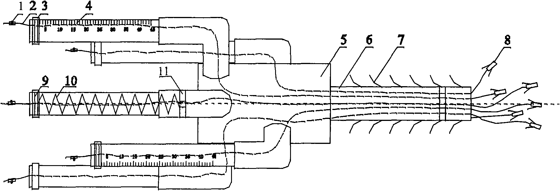
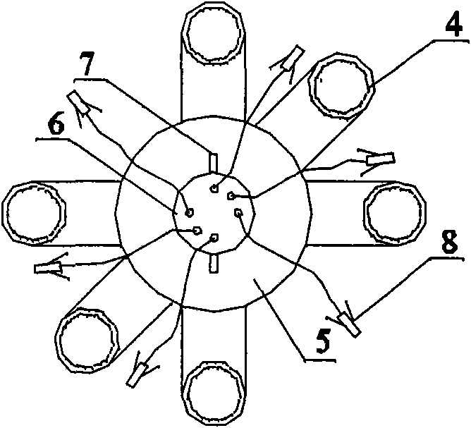
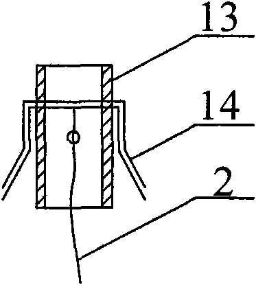
Description

technical field

[0001] The invention relates to a rotary disc type deep base point displacement meter and a measuring method, and is especially suitable for measuring the axial displacement of the surrounding rock or the interior of the foundation along the drilling hole and monitoring the stability of the shafts, tunnels, chambers and foundation engineering. Background technique

[0002] Due to its simple structure, the displacement meter is widely used in underground engineering. It is mostly used in underground engineering such as mines, tunnel traffic, and large-span chambers. It is used to monitor the deformation of roadways and chambers, and provides reliable information for safe production and support design. parameter. At present, the measurement of the displacement of the surrounding rock around the underground project adopts the drilling measurement technology, that is, a measurement borehole is constructed on the surrounding rock to be measured, and the base point...

Examples

Embodiment Construction

[0024] An embodiment of the present invention will be further described below in conjunction with accompanying drawing:

[0025] figure 1 figure 2 As shown, the turntable deep base point displacement gauge is mainly composed of a measuring cylinder 4, an orifice device 5, a fixer 6, a base point anchor head 8 and a measuring connection line 2. Measuring cylinders 4 are arranged in a circular shape with different lengths and scales are displayed on the outer surface. There are five or six measuring cylinders 4, and the length of each measuring cylinder 4 is set according to actual measurement requirements. One end of the six measuring cylinders 4 is respectively fixed on the casing of the orifice device 5, and its axis is parallel to the axis of the orifice device 5. A vernier slip ring 3 is installed on the measuring cylinder 4, and a stopper 9 and The retaining ring 11, the spring 10 is connected between the retaining block 9 and the retaining ring 11; the orifice device 5...