Optical continuous water quality analytical system

A technology for water quality analysis and analysis system, which is applied in the direction of material analysis, analysis materials, and scientific instruments through optical means. Range, the effect of raising the upper limit of measurement

Inactive Publication Date: 2010-12-15
FOCUSED PHOTONICS
View PDF0 Cites 0 Cited by
  • Summary
  • Abstract
  • Description
  • Claims
  • Application Information

AI Technical Summary

Problems solved by technology

Such device also has some deficiencies: 1) measurement range is small; In order to measure the water sample that COD is less, need to use longer measuring light path, but at this moment, the water sample of high COD value is too strong to the absorption of ultraviolet light, As a result, the light signal through the water sample is weak or absent, making it impossible to measure; 2) It is impossible or difficult to measure water samples with high concentrations of COD, because it is difficult to design a small measurement optical path, and the pollutants in the water samples will contaminate The measurement window leads to a large relative change in the measurement optical path, thereby reducing the measurement accuracy; 3) The application field of the device is narrow. Due to the limitation of the measurement range and the upper limit of the measurement, it is impossible to complete the water quality analysis in many fields, such as the water at the entrance of the wastewater treatment plant. Water quality analysis, etc.

Method used


Image

  • Optical continuous water quality analytical system
  • Optical continuous water quality analytical system
  • Optical continuous water quality analytical system

Examples


Embodiment 1

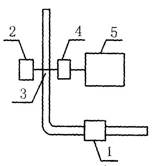
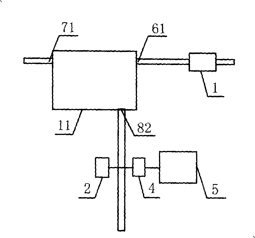
[0024] like Figure 2 to Figure 4 As shown, an optical continuous water quality analysis system is used to analyze the value of COD in water samples. The analysis system includes a sampling device 1 , a measuring device, an analysis device 5 and a sample dilution device 11 . The sampling device 1 adopts a peristaltic pump; the measuring device includes an ultraviolet light source 2 , a measuring pool 3 and a light receiving device 4 .

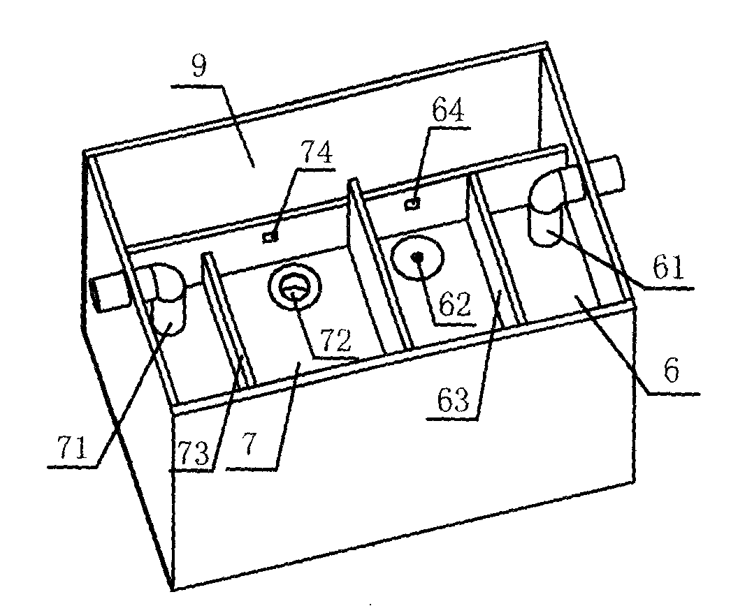
[0025] Described dilution device 11 is installed between described sampling device 1 and measuring device, comprises measured water sample case 6, dilution liquid case 7 (this embodiment adopts clean tap water to dilute), water storage tank 8, overflow case 9, mixing Device 10, filter screen 63 and partition 73.

[0026] The tested water sample box 6 is provided with an inlet 61, an outlet 62 and an overflow 64, the inlet 61 is positioned at one side of the tested water sample box 6, and the outlet 62 is located at the bottom of the tested wa...

Embodiment 2

[0036] like figure 2 and Figure 5 As shown, an optical continuous water quality analysis system is different from Example 1 in that the water storage tank is no longer used, and the water flowing out from the measured water sample tank and the diluted liquid tank flows through the "Y" mixing device after being fully mixed. downstream measuring devices for analysis.

Embodiment 3

[0038] like figure 2 and Image 6 As shown, an optical continuous water quality analysis system is different from Embodiment 1 in that the mixing device is a funnel device 12, and the water flowing out from the outlets 62, 72 flows into the funnel and passes through the vertical pipe 121 The mixer (not shown) inside flows into the water storage tank 8 after being fully mixed. The height of the inlet of the funnel device 12 is higher than the height of the overflow port 84 of the water storage tank 8 . In addition, the aperture size of the outlet of the funnel device is designed so that the fluid flowing into the funnel device does not overflow.


PUM


Abstract

The invention discloses optical continual water quality analysis system. It includes sampling device, measuring device, and analyzing device. The analyzing device includes diluting device which is formed by measured water sample box, diluting liquid box, and mixing device. Both of the former two are set flow inlet, discharge flow port, and overflow port. And the last one is set flow inlet and discharge flow port. The measured water sample and diluted liquid ran out from the discharge flow port of the measured water sample box and diluting liquid box are flowed into the flow inlet of the mixing device.

Description

technical field [0001] The invention relates to a water quality analysis system, in particular to an optical continuous water quality analysis system. Background technique [0002] like figure 1 As shown, a commonly used water quality COD detection system includes a sampling device 1, a measuring device and an analyzing device 5. The sampling device 1 usually adopts a peristaltic pump; the measuring device includes a measuring cell 3 , an ultraviolet light source 2 , and a light receiving device 4 . The water sample to be measured flows through the measurement pool 3 from bottom to top after being sampled by the peristaltic pump 1, and the ultraviolet light source 2 on one side of the measurement pool 3 emits light. The light receiving device 4 on the side receives it, and the received signal is sent to the analysis device 5 for analysis, and then the COD value in the tested water sample is obtained. Such device also has some deficiencies: 1) measurement range is small; I...

Claims


Application Information

Patent Timeline
Patent Type & Authority Patents(China)
IPC IPC(8): G01N1/38G01N21/00
Inventor 李增珍王磊叶华俊王健
Owner FOCUSED PHOTONICS
Why Eureka
Try Eureka