Polarizer capable of realizing high polarization extinction ratio, manufacturing method and testing device thereof

A polarization extinction ratio and testing device technology, which is applied in polarizing components, testing optical properties, optics, etc., can solve the problems of low measurement upper limit and inability to meet the requirements of accurate measurement of polarization extinction ratio, so as to improve performance and increase the measurement upper limit Effect

Active Publication Date: 2017-07-28
THE 44TH INST OF CHINA ELECTRONICS TECH GROUP CORP
View PDF2 Cites 0 Cited by
  • Summary
  • Abstract
  • Description
  • Claims
  • Application Information

AI Technical Summary

Problems solved by technology

[0003] The rotating analyzer method is the main technical means to test the polarization extinction ratio in the prior art, and its principle is as follows: figure 1 As shown, the input optical interface, collimating lens, polarizing prism and photodetector are arranged on the same optical axis according to the arrangement in the figure, and the rotating motor controls the rotation of the polarizing prism so that two mutually orthogonal polarization components in the incident beam alternately pass through the polarized light The prism is incident into the photodetector, and the optical power P of two mutually orthogonal polarization components is obtained after the signal processing circuit max and P min , according to the formula ER=10×lg (P max / P min ) can calculate the polarization extinction ratio of the incident light; the existing problem is: in the prior art, the polarization extinction ratio of the polarizing prism used in the aforementioned rotating analyzer method can only reach 55dB at the highest, and due to the unavoidable There are assembly errors, so the maximum polarization extinction ratio that can be measured by the polarization extinction ratio test device based on the aforementioned polarizing prism is generally lower than 55dB, which makes the measurement upper limit of the polarization extinction ratio test device lower, which is far from meeting the needs of modern precision optics. Requirements for accurate measurement of polarization extinction ratio in the system

Method used


Image

  • Polarizer capable of realizing high polarization extinction ratio, manufacturing method and testing device thereof
  • Polarizer capable of realizing high polarization extinction ratio, manufacturing method and testing device thereof
  • Polarizer capable of realizing high polarization extinction ratio, manufacturing method and testing device thereof

Examples


Embodiment Construction

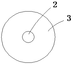
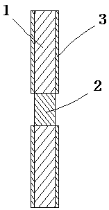
[0027] A polarizer capable of achieving a high polarization extinction ratio, the innovation of which is: the substrate of the polarizer is a lithium niobate wafer 1 cut from a lithium niobate crystal; the lithium niobate wafer 1 is a sheet structure The middle part of the lithium niobate wafer 1 is provided with a columnar optical waveguide region 2, the axial direction of the optical waveguide region 2 is perpendicular to the large plane of the lithium niobate wafer 1, and the optical waveguide region 2 runs through the lithium niobate wafer 1; the lithium niobate wafer The area other than the optical waveguide area 2 on the large plane of 1 is covered with a light-blocking film layer 3; the diameter of the optical waveguide area 2 is 4 to 100mm; the large plane of the lithium niobate wafer 1 is tangential to or X-Z tangentially parallel.

[0028] Further, the cross-section of the optical waveguide region 2 is circular, the diameter of the optical waveguide region 2 is 4-100...


PUM


Abstract

The invention discloses a polaroid high in polarization extinction ratio. A substrate of the polaroid is made of lithium niobate wafer cut from lithium niobate crystal. The lithium niobate wafer is in the sheet structure. The middle of the lithium niobate wafer is provided with a column optical waveguide area. The axis direction of the optical waveguide area is perpendicular to a large plane of the lithium niobate wafer. The optical waveguide are penetrates the lithium niobate wafer. Outside the optical waveguide area, the large plane of the lithium niobate wafer is covered with a light-resistant film layer. The large plane of the lithium niobate wafer is parallel to a tangential direction Y-Z or a tangential direction X-Z of the lithium biobate wafer. The polaroid has the advantages that the conventional polarizing prism of a polarization extinction ratio test device is replaced, a test upper limit of the polarization extinction ratio test device is increased, and property of the polarization extinction ratio test device is improved.

Description

technical field [0001] The invention relates to a polarization extinction ratio testing technology, in particular to a polarizer capable of realizing a high polarization extinction ratio, a manufacturing method and a testing device. Background technique [0002] With the continuous development of laser polarization technology, polarizers are more and more widely used in the fields of light sensing, photoelectric information processing and optical communication. Polarization extinction ratio is the most important performance index to evaluate the performance of polarizing devices. Fast and accurate measurement of polarization extinction ratio of polarizing devices is one of the problems to be solved in the application field of laser polarization technology. [0003] The rotating analyzer method is the main technical means to test the polarization extinction ratio in the prior art, and its principle is as follows: figure 1 As shown, the input optical interface, collimating le...

Claims


Application Information

Patent Timeline
Patent Type & Authority Patents(China)
IPC IPC(8): G02B5/30G01M11/02
CPCG01M11/02G02B5/3041
Inventor 华勇田自君张征乔海燕
Owner THE 44TH INST OF CHINA ELECTRONICS TECH GROUP CORP
Why Eureka
Try Eureka