
Locking structure of electronic device

A technology of an electronic device and a resisting block, which is applied in the direction of electrical equipment shell/cabinet/drawer, telephone communication, electrical components, etc., can solve the problems such as the sliding of the cover body 20 and the insufficient stability and reliability of the lock, and achieve the effect of convenient opening

Inactive Publication Date: 2009-10-28
SHENZHEN FUTAIHONG PRECISION IND CO LTD
View PDF0 Cites 2 Cited by
  • Summary
  • Abstract
  • Description
  • Claims
  • Application Information

AI Technical Summary

Problems solved by technology

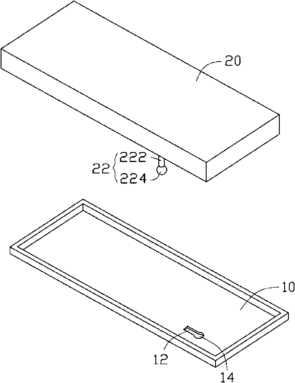
[0005] However, after the cover 20 is installed on the housing 10 in this structure, the cover 20 is prone to slide relative to the housing 10, and the locking is not stable and reliable enough.

Method used


Image

  • Locking structure of electronic device
  • Locking structure of electronic device
  • Locking structure of electronic device

Examples


Embodiment Construction

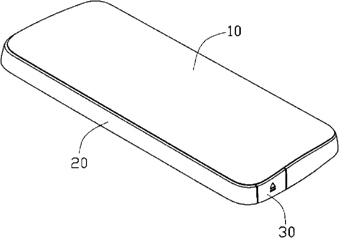
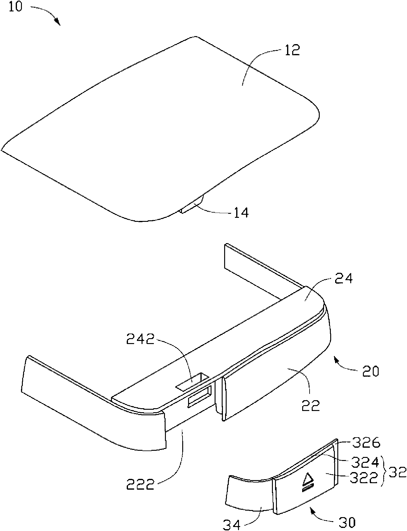
[0014] see figure 2 According to a preferred embodiment of the present invention, a locking device for an electronic device includes a battery cover 10 , a housing frame 20 and a pressing body 30 . The battery cover 10 is locked on the housing frame 20 through the pressing body 30 .

[0015] see image 3 and Figure 4 , the battery cover 10 includes a plate portion 12 and a hook 14 disposed on the plate portion 12 . The plate portion 12 is formed with a peripheral edge 122 . The hook 14 protrudes from the bottom surface of the plate portion 12 adjacent to the peripheral edge 122 . The hook 14 has certain elasticity and includes a main body 142 and a hooking portion 144 . The hooking portion 144 is formed on a side of the main body 142 , and forms an inclined surface relative to the main body 142 , so that the hook 14 is easily inserted.

[0016] The casing outer frame 20 is roughly a rectangular frame structure, which is fixedly connected to the main body (not shown) of...


PUM


Abstract

The invention discloses a locking structure of an electronic device, which is used for locking a cover body of the electronic device to a shell outer frame. The locking structure comprises the cover body, the shell outer frame and a pressing body, wherein a clamping hook is formed on the cover body; the shell outer frame is provided with an end wall and a connecting wall; the connecting wall is fixedly connected to the shell outer frame, and a section of cut section parallel to the shell outer frame extends; the connecting wall is provided with a clamping hole; the pressing body is provided with a butting block; the cover body is arranged on the shell outer frame; the clamping hook is clamped into the clamping hole; the pressing body is matched with the cut; the butting block is sleeved into the clamping hole and butts the clamping hook; and the butting block pushes the clamping hook to separate from the clamping hole by pressing the pressing body so as to make the cover body opened relatively to a body. The locking structure of the electronic device makes the cover body stably locked relatively to a shell and is convenient for opening the cover body.

Description

technical field [0001] The present invention relates to a locking structure of an electronic device, in particular to a locking structure for locking and unlocking a cover of an electronic device. Background technique [0002] Portable electronic devices are equipped with covers that need to be opened frequently, such as battery covers, camera lens covers, and the like. The lock between the cover and the housing of the electronic device generally adopts hooks and slots. It is more common to arrange hooks on the side wall and both ends of the cover body. The hooks have an "arrowhead" structure with a thin head and a wider tail than the head. The side wall of the housing and the two ends of the electronic device are provided with slots corresponding to the hooks of the cover. By pushing the cover, the head of the hook of the cover first slides into the slot on the side wall of the housing of the electronic device, and then the tail of the hook slides into the slot and abuts ...

Claims


Application Information

Patent Timeline
Patent Type & Authority Applications(China)
IPC IPC(8): H05K5/00H05K5/03
CPCH04M1/0252Y10T292/1059
Inventor 施政张智强
Owner SHENZHEN FUTAIHONG PRECISION IND CO LTD
Learn More