Groove suction vane for pump

A technology of grooves and vanes, which is applied in the field of grooved drainage vanes, can solve problems affecting pump performance and unfavorable flow separation, etc.

Inactive Publication Date: 2009-11-04
金华昶勋流体机械有限公司
View PDF0 Cites 10 Cited by
  • Summary
  • Abstract
  • Description
  • Claims
  • Application Information

AI Technical Summary

Problems solved by technology

However, studies have shown that the angle of attack of incoming flow significantly affects the performance of the pump, and at the same time it is easy to cause unfavorable flow separation

Method used


Image

  • Groove suction vane for pump
  • Groove suction vane for pump
  • Groove suction vane for pump

Examples


Embodiment Construction

[0016] In order to make the technical means, creative features, goals and effects achieved by the present invention easy to understand, the present invention will be further described below in conjunction with specific illustrations.

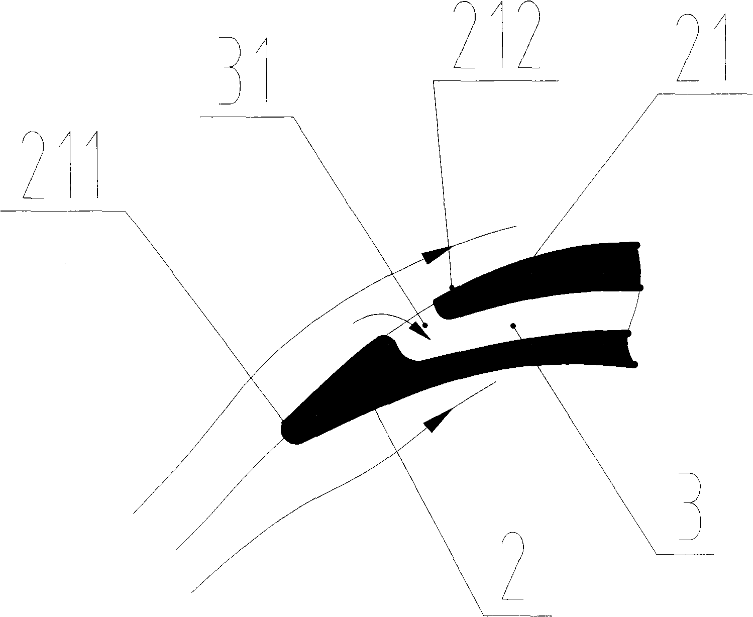
[0017] see image 3 and Figure 4 , an impeller of a pump, including an impeller hub 1 connected to a pump shaft and blades 2 evenly distributed on the impeller hub 1 . The number of blades 2 is four, five or six, or other numbers, which are mainly set according to the design requirements of the pump. The position of the vane 2 in the impeller hub 1 and the shape and size of the vane 2 are no different from the existing pump impeller, which is not the focus of the present invention, and is very well known to those skilled in the art, so it will not be described in detail here describe. As the impeller of the centrifugal pump, it also includes a front cover plate 4 , which is connected and fixed with the blades 2 .

[0018] The pump impeller ...


PUM


Abstract

The invention discloses a groove suction vane for a pump, which comprises a vane integrated with an impeller hub of the pump into a whole by fixation, and 1 to 3 grooves are arranged on the vane. Blocked fluid in a boundary layer is sucked by using the grooves, and a new boundary layer is also formed on the back of the grooves and can bear the counter pressure gradient of the fluid without separation. The sucking grooves designed and arranged according to the invention can radically eliminate the separation. As no separation zone exists, the pressure resistance can be greatly reduced. The groove suction vane realizes improving the performance of the pump in a larger operating range.

Description

technical field [0001] The invention relates to the technical field of pumps, in particular to a pump grooved flow vane. Background technique [0002] When the traditional pump is running, the best flow conditions can be obtained by adjusting the angle of attack of the flow. However, studies have shown that the angle of attack of the incoming flow significantly affects the performance of the pump, and at the same time it is easy to cause unfavorable flow separation. Such as figure 1 As shown, the angle of attack of the incoming flow causes the separation of the boundary layer of the moving blade, and the resulting vortex region is one of the most important factors causing energy loss. To analyze this phenomenon in detail: figure 2 As shown, the viscous friction stagnates the forward movement of the fluid, and the pressure also blocks the forward movement of the fluid, the fluid particle decelerates continuously, and finally stops at point S. The stopped fluid accumulate...

Claims


Application Information

Patent Timeline
Patent Type & Authority Applications(China)
IPC IPC(8): F04D29/24
Inventor 陈红勋见文张洪博魏培茹
Owner 金华昶勋流体机械有限公司
Why Eureka
Try Eureka