
Digital display water tap

A faucet and faucet technology, applied in valve details, engine components, multi-way valves, etc., can solve problems such as the inability to intuitively judge the water temperature and the simple water control function.

Inactive Publication Date: 2011-01-26
XIAMEN SOLEX HIGH TECH IND CO LTD
View PDF0 Cites 0 Cited by
  • Summary
  • Abstract
  • Description
  • Claims
  • Application Information

AI Technical Summary

Problems solved by technology

At present, the domestic waterway uses a water meter to display the overall water flow rate, but the water flow rate of each branch cannot be known. Because the connecting pipe of the traditional water meter is a standard part, it must be connected to the standard water inlet pipe to realize the flow measurement. In addition, today's household faucets only have a simple water outlet control function, and the choice of hot and cold water is controlled by adjusting the water outlet ratio of the faucet's cold and hot water, and directly feeling the water temperature with hands to select the temperature of the required water outlet, which cannot be intuitive. Determine the temperature of the water

Method used


Image

  • Digital display water tap
  • Digital display water tap
  • Digital display water tap

Examples


Embodiment Construction

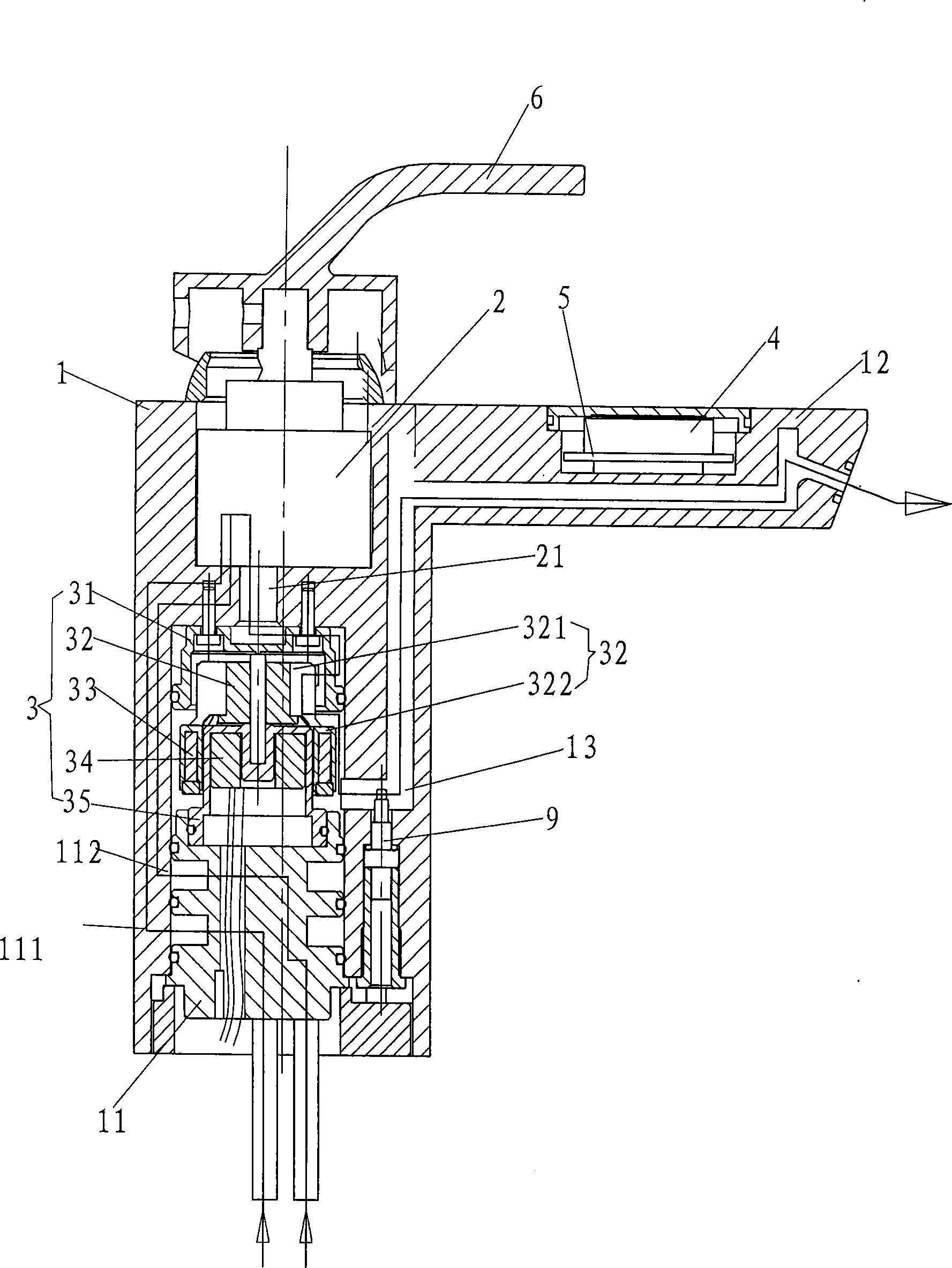
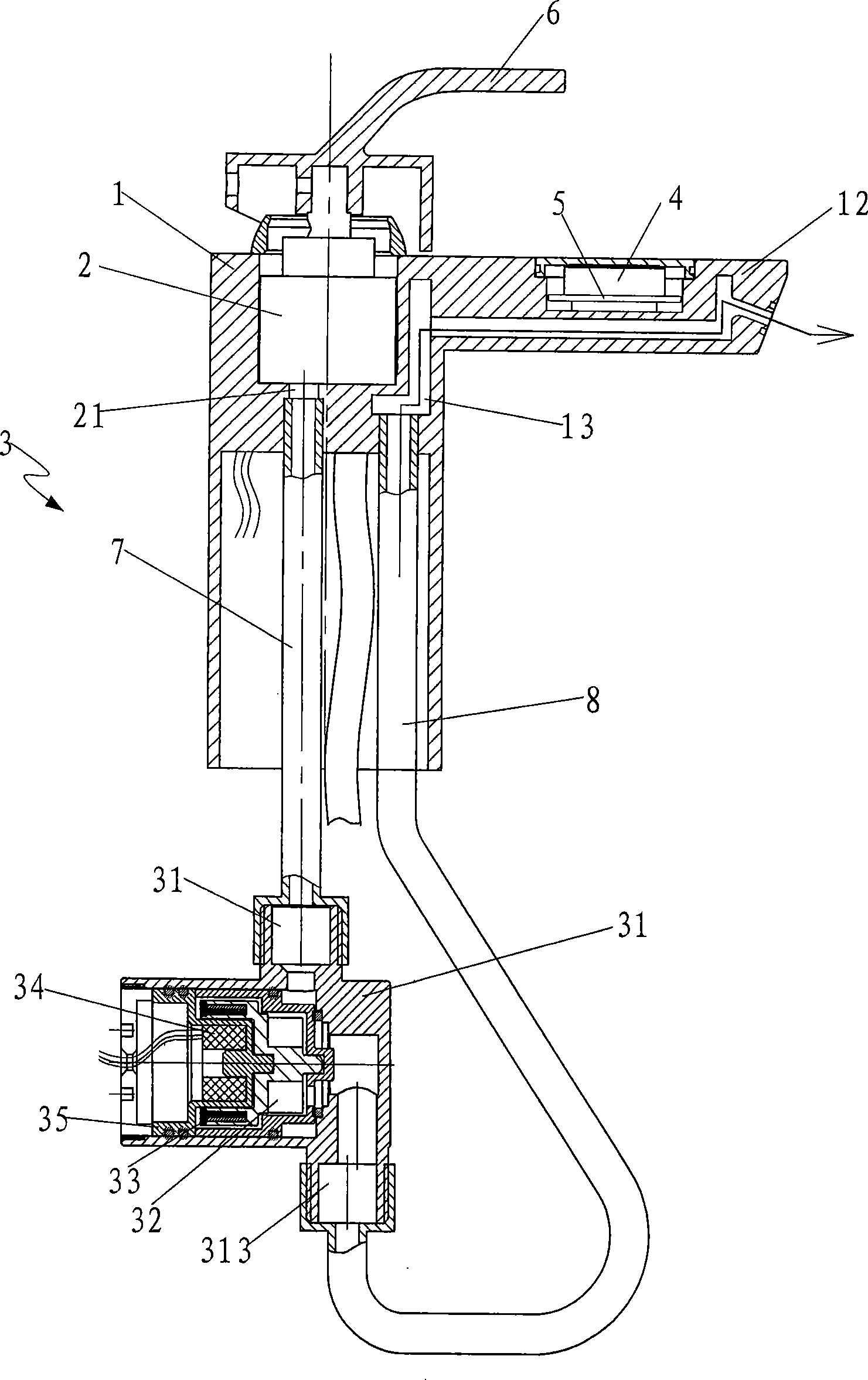
[0021] Such as figure 1 , 2, the light-emitting faucet of the present invention includes a faucet body 1, a valve core 2, a power generation valve body 3, an LCD liquid crystal display panel 4 and a circuit control panel 5.

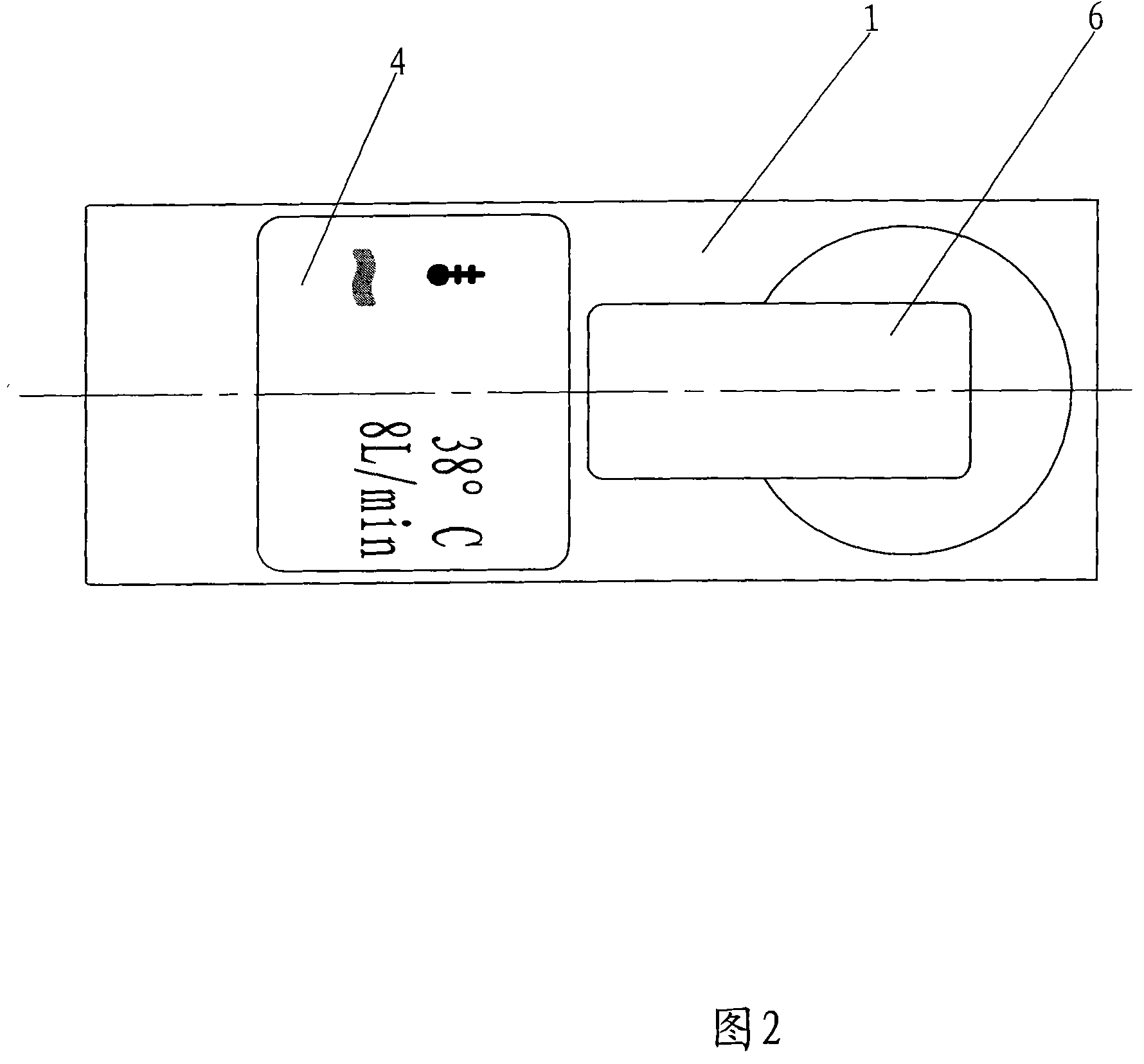
[0022] The upper part of the faucet body 1 is connected to the control handle 6, and the control handle 6 is connected with the valve core 2 placed in the faucet body 1 to control the water inlet and outlet of the valve core 2. There is a water inlet block 11, the water inlet block 11 is provided with two water inlets 111, 112 to communicate with the two water inlets of the valve core 2, and the water inlets 111, 112 are connected with external hot and cold water pipes; at the front of the faucet body 1 is The faucet outlet 12 is provided with an LCD liquid crystal display board 4 and a circuit control board 5 above the faucet water outlet 12. The circuit control board 5 is located below the LCD liquid crystal display board 4 and the two are connected; T...


PUM


Abstract

The invention relates to a digital display water tap which comprises a tap body, a valve core, a power-generating valve body and an LCD display panel, wherein a circuit control panel is communicated below the LCD display panel, and the circuit control panel and the LCD display panel are together assembled at the upper part in front of the tap body; the valve core is fixed in the tap body and controls water drain by a control handle on the tap body, a water outlet of the valve core is connected with the power-generating valve body, and the power-generating valve body is connected with a water outlet pipeline of the tap body; an impeller, a permanent magnet, a winding and a winding sleeve are arranged in the power-generating valve body; the impeller is pivoted in the power-generating valve body, and the permanent magnet is fixed in the impeller; the winding is fixed in the power-generating valve body by the winding sleeve and arranged at the position of the permanent magnet of the impeller; and the circuit control panel is connected with the winding by a lead so as to achieve an electric appliance loop. The voltage generated by driving a microgenerator assembly by utilizing the hydraulic pressure, the kinetic energy and the potential energy of a water circuit system can drive the LCD display panel to display the water drain flow and the temperature of the water tap, and the magnitude of the water drain flow can be calculated by the different frequencies of hydraulic power generation current due to a rotating speed difference of a motor.

Description

technical field [0001] The invention relates to a faucet structure, in particular to a digital display faucet capable of displaying water flow and water flow temperature. Background technique [0002] With the improvement of living standards and the development of science and technology, consumers pay more and more attention to the diversity of functions when choosing household products. At present, the domestic waterway uses a water meter to display the overall water flow rate, but the water flow rate of each branch cannot be known. Because the connecting pipe of the traditional water meter is a standard part, it must be connected to the standard water inlet pipe to realize the flow measurement. In addition, today's household faucets only have a simple water outlet control function, and the choice of hot and cold water is controlled by adjusting the water outlet ratio of the faucet's cold and hot water, and directly feeling the water temperature with hands to select the tem...

Claims


Application Information

Patent Timeline
Patent Type & Authority Patents(China)
IPC IPC(8): F16K37/00F16K27/00F16K11/02F16K31/60F03B13/00
Inventor 童灯亮
Owner XIAMEN SOLEX HIGH TECH IND CO LTD
Learn More