
Hidden failure diagnostic method of digital transformer protector measuring loop

A transformer protection and hidden fault technology, applied in the direction of fault location, etc., can solve the problems of protection device malfunction, refusal to operate, digital transformer protection device malfunction, etc.

Active Publication Date: 2009-11-11
CHONGQING UNIV +1
View PDF0 Cites 25 Cited by
  • Summary
  • Abstract
  • Description
  • Claims
  • Application Information

AI Technical Summary

Problems solved by technology

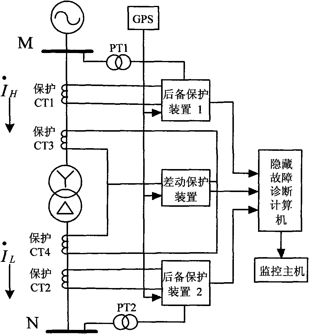
At this time, the hidden faults existing in the CT (PT) measurement circuit, connecting cables and connecting terminals, pre-processing circuit of the protection device, sampling and sampling value calculation may not necessarily cause the protection device to malfunction, but when the primary current increases When there is a large fault or a fault outside the protection zone, such hidden fault will be activated, causing the digital transformer protection device to malfunction or refuse to operate

Method used


Image

  • Hidden failure diagnostic method of digital transformer protector measuring loop
  • Hidden failure diagnostic method of digital transformer protector measuring loop
  • Hidden failure diagnostic method of digital transformer protector measuring loop

Examples


Embodiment 1

[0210] Embodiment 1: In formula (7-1)

[0211] g 1a = 1

[0212] If established, it indicates that there is a hidden fault in the phase a current measurement circuit of the backup protection device (1).

Embodiment 2

[0213] Embodiment 2: In formula (7-1,7-2,7-3)

[0214] g 3a = 1

[0215] g 3b = 1

[0216] g 3c = 1

[0217] If both are established, it means that there are hidden faults in the three-phase current measurement circuits on the high voltage side of the differential protection device.

[0218] 2. Analysis of hidden fault diagnosis results of voltage measurement circuit;

Embodiment 3

[0219] Embodiment 3: In formula (12-1)

[0220] g Ua = 1

[0221] If established, it indicates that there is a hidden fault in the backup protection device (1) or the a-phase voltage measurement circuit of the backup protection device (2).

[0222] 3. The alarm output mode of hidden fault diagnosis results, when the hidden fault diagnosis computer detects that there is a hidden fault in the measurement circuit of the corresponding protection device through analysis and comparison of the measured values ​​of the digital transformer differential protection device and the backup protection device (1) and (2). When a fault occurs, the hidden fault diagnosis computer sends hidden fault information to the monitoring host, and the monitoring host sends out an alarm signal corresponding to the differential protection device and the backup protection device (1), (2) that there is a hidden fault in the measurement circuit.


PUM


Abstract

The invention provides a hidden failure diagnostic method of a digital transformer protector measuring loop, which belongs to the technical field of secondary power device failure diagnosis. The hidden failure diagnostic method comprises the following steps: 1. a hidden failure diagnostic computer collects the current measuring value amplitude at the high voltage side and the low voltage side of a differential protector of the digital transformer and the current and voltage measuring values of a back-up protector (1) and a back-up protector (2) in real time; 2. the collected current and voltage measuring values are respectively analyzed and compared by a method of analysis of variance according to the relativity of the input information of the differential protector as well as the back-up protector (1) and the back-up protector (2); and 3. the hidden failure diagnostic result is analyzed and outputted. The method can monitor whether the current and voltage measuring values of the digital transformer protector as well as the back-up protector (1) and the back-up protector (2) are normal or not in real time and judge whether the measuring loops of the digital transformer protector as well as the back-up protector (1) and the back-up protector (2) have failure or not hereby.

Description

Technical field: [0001] The invention relates to a hidden fault diagnosis method for a measuring circuit of a digital transformer protection device. The invention belongs to the technical field of electric power secondary equipment fault diagnosis. technical background: [0002] As the first line of defense for the safety and stability of the power grid, the relay protection device plays a very important role. The possible hidden faults of relay protection devices contribute to the expansion of chain reaction accidents, and the direct consequence is the wrong disconnection of the protected components. In order to improve the operational reliability of the power system, it is of great significance to realize the detection and monitoring of hidden faults in relay protection devices to ensure the safety of the power grid. In recent years, the construction of relay protection information system is proceeding rapidly, and the information of relay protection devices is expected ...

Claims


Application Information

Patent Timeline
IPC IPC(8): G01R31/08
Inventor 熊小伏字美荣沈智健罗曦吴玲燕彭晓宇徐佳
Owner CHONGQING UNIV
Learn More