Auxiliary tool for dismounting CPU

A jig and guide mechanism technology, applied in the jig field, can solve the problems of easily damaged CPU pins, difficult to pull out the CPU horizontally, and scrapped electronic components, etc., to achieve the effect of improving the efficiency of functional testing and easy operation.

Inactive Publication Date: 2009-11-11
MITAC COMP (SHUN DE) LTD
View PDF0 Cites 8 Cited by
  • Summary
  • Abstract
  • Description
  • Claims
  • Application Information

AI Technical Summary

Problems solved by technology

[0003] After the CPU is inserted into the corresponding slot on the motherboard, the 370 pins of the CPU are closely matched with the corresponding 370 slots of the Socket, and the gap between the two is very small. The original disassembly method is to use tools such as blades Direct disassembly, this method is difficult to keep the CPU pulled out horizontally during disassembly, and it is easy to damage the pins of the CPU during the disassembly process, resulting in the scrapping of electronic components

Method used


Image

  • Auxiliary tool for dismounting CPU
  • Auxiliary tool for dismounting CPU
  • Auxiliary tool for dismounting CPU

Examples


Embodiment Construction

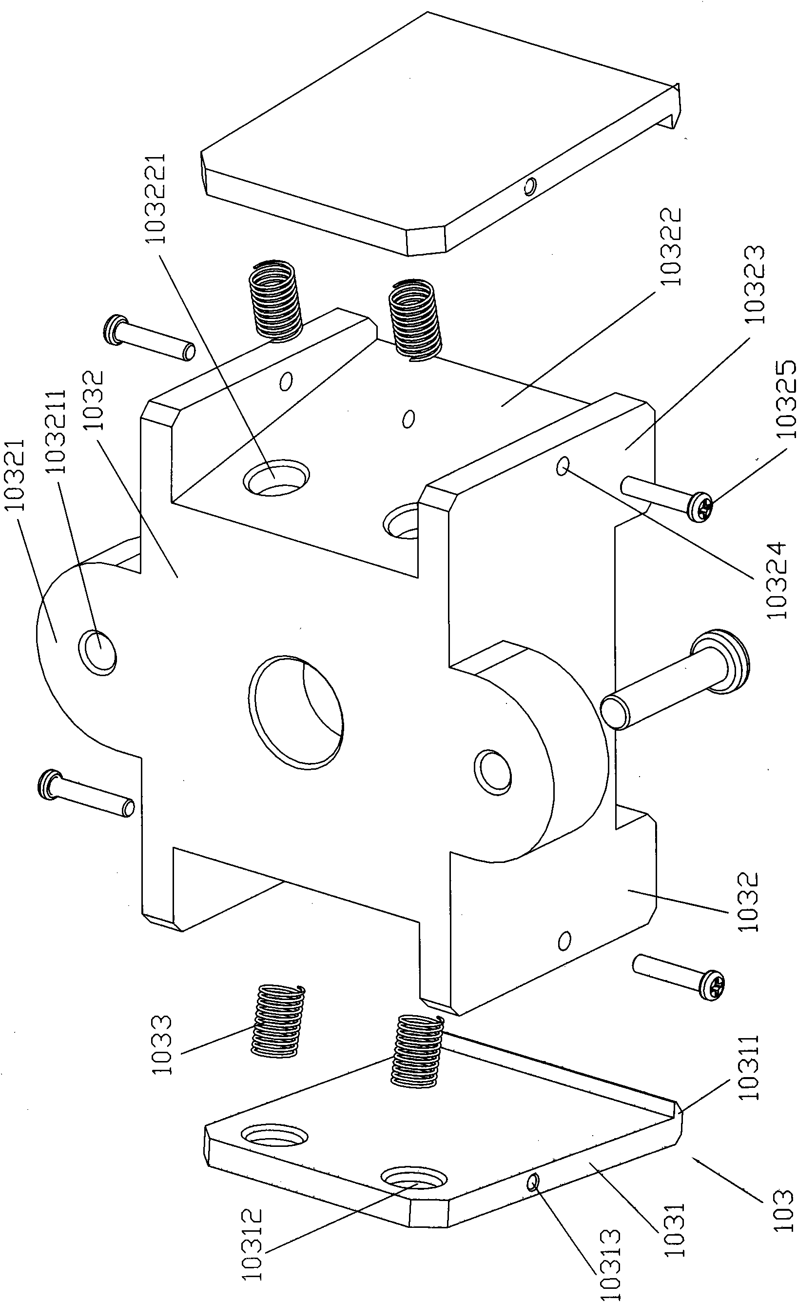
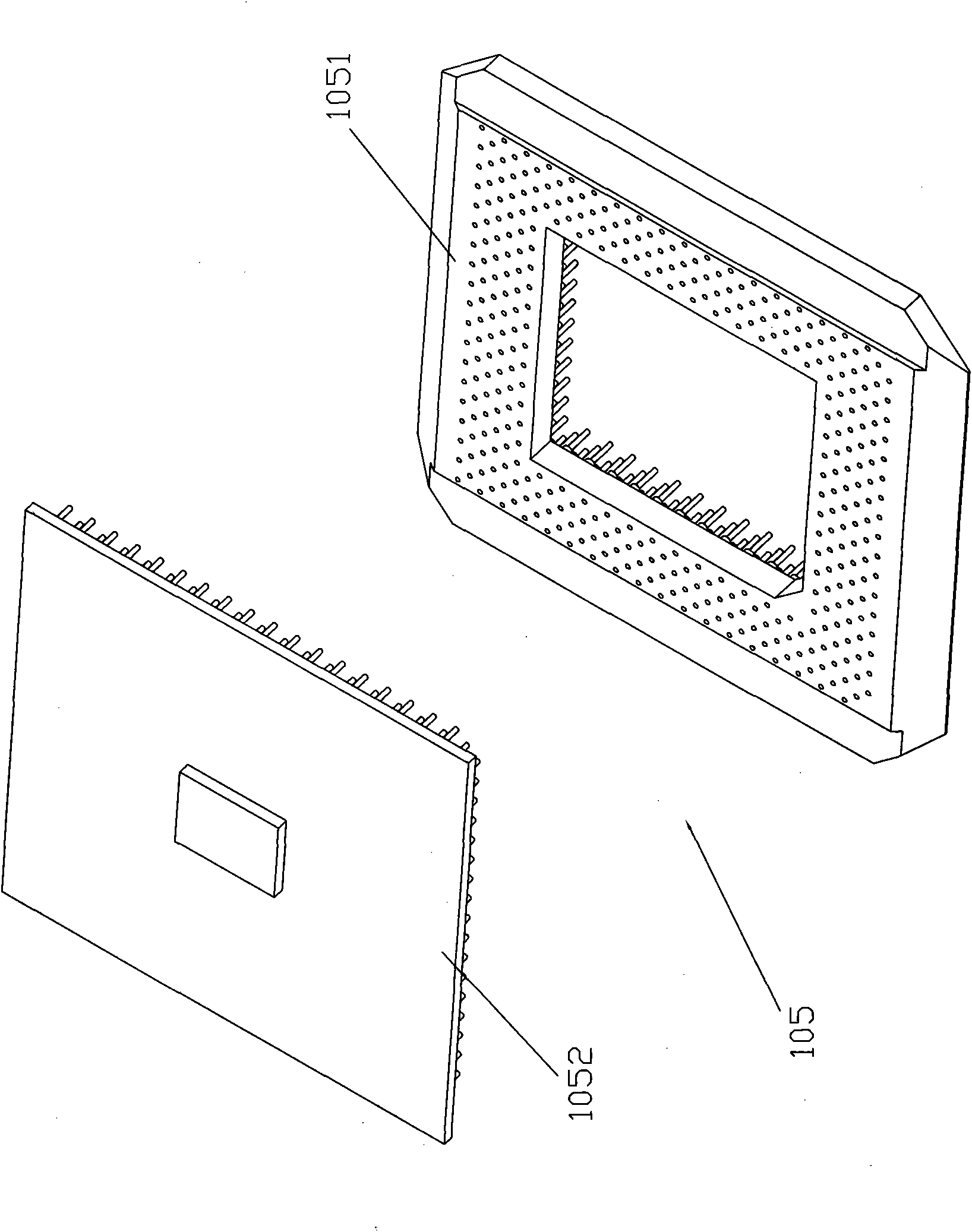
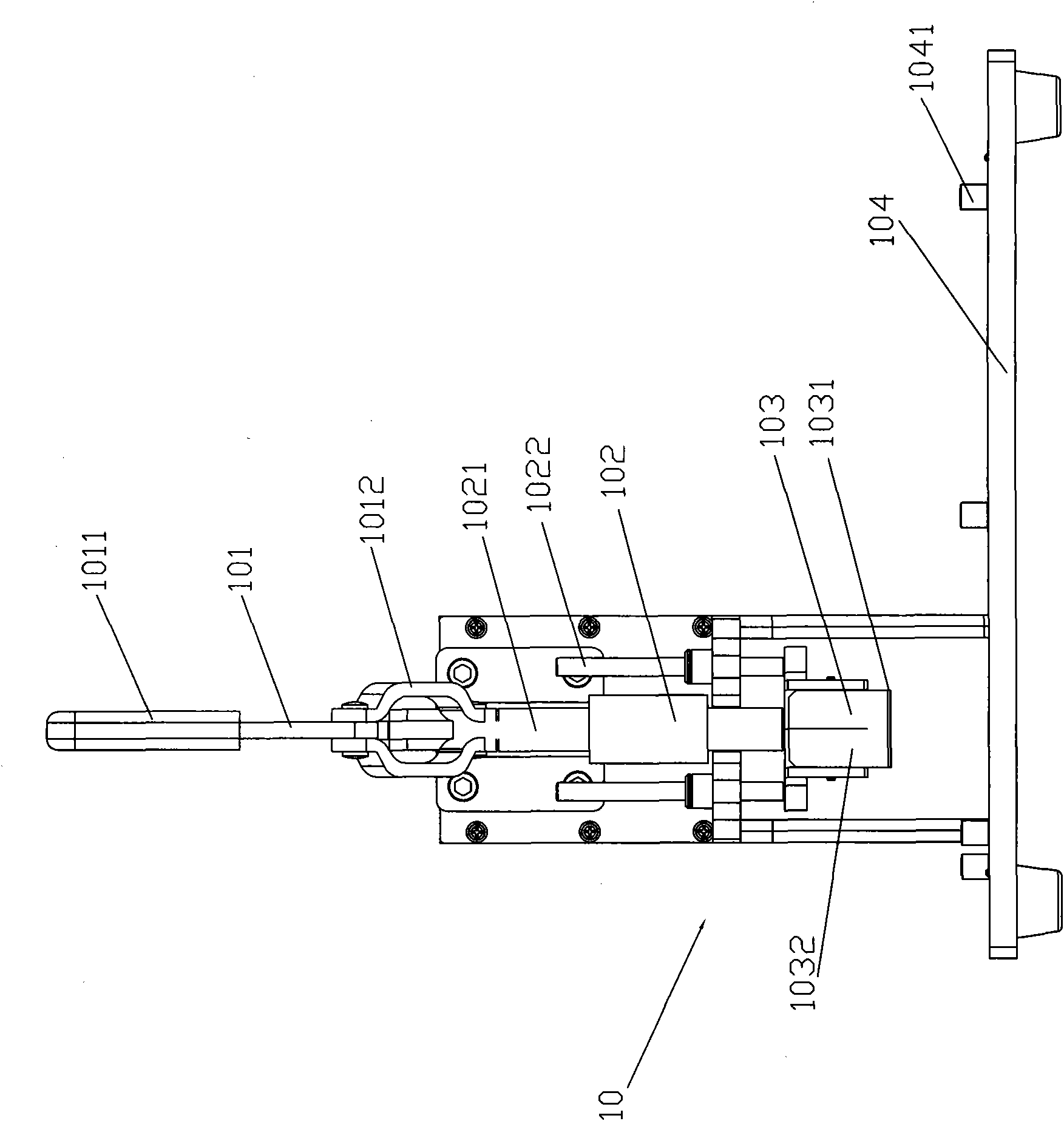
[0013] Please also refer to figure 1 , figure 2 , image 3 , Figure 4 and Figure 5 shown. The auxiliary dismantling CPU jig 10 described in the present invention is mainly suitable for disassembling the CPU on the main board 20 to be tested after a main board 20 to be tested has been functionally tested. The auxiliary dismantling jig 10 mainly includes a movable mechanism 101, A guiding mechanism 102 , a clamping mechanism 103 and a fixing base 104 .

[0014] Wherein, the fixed base 104 is provided with a receiving groove (not shown in the figure) and a plurality of holding parts 1041 arranged around the receiving groove, and the holding parts 1041 can be movably rotated on the surface of the fixing base 104, A number of positioning pins (not shown) are arranged in the accommodating groove for placing the main board 20 to be tested and using the positioning pins therein to fix the main board 20 to be tested. Rotate the holding part 1041 by hand, Until the pressing por...


PUM


Abstract

The invention provides an auxiliary tool for dismounting a CPU, which mainly comprises a guide mechanism, a moving mechanism, a clamping mechanism, an overhead hook and a plurality of elastic elements, wherein the moving mechanism is connected with one end of the guide mechanism so as to provide power for the guide mechanism to move up and down; the clamping mechanism mainly comprises a body and two clamping wings, the body is connected with the other end of the guide mechanism, and two opposite sides of the clamping mechanism are set to be inclined surfaces; the clamping wings are respectively arranged on the inclined surfaces, and one lateral margin of each of the two clamping wings respectively extends to be provided with the overhead hook for hooking and buckling the CPU of a mainboard; and the electric elements are fixed between each inclined surface and each clamping wing. The auxiliary tool for dismounting a CPU also comprises a CPU transferring card for combining and splicing with the CPU. In the invention, the CPU and the CPU transferring card are pulled out horizontally, thereby not only the operation is simple and easy, but also the CPU is avoided to be damaged, and the functional test efficiency is effectively improved.

Description

technical field [0001] The invention relates to a jig, in particular to a jig for assisting the disassembly of a CPU in a function test. Background technique [0002] Generally, when doing a functional test of the mainboard, take the Dot hill212 mainboard as an example for BFT testing. During the test, a CPU with 370 pins needs to be inserted into the corresponding slot (ie Socket) on the mainboard before the mainboard can be tested. A series of functional tests. After the test is completed, the CPU still needs to be disassembled from the motherboard to conduct the next round of functional tests on another motherboard. [0003] After the CPU is inserted into the corresponding slot on the motherboard, the 370 pins of the CPU are closely matched with the corresponding 370 slots of the Socket, and the gap between the two is very small. The original disassembly method is to use tools such as blades Direct disassembly, in this way, it is difficult to keep the CPU pulled out hori...

Claims


Application Information

Patent Timeline
Patent Type & Authority Applications(China)
IPC IPC(8): G06F11/26H05K7/14
Inventor 黄承禄
Owner MITAC COMP (SHUN DE) LTD
Why Eureka
Try Eureka