
Composite connector for memory cards

A memory card and connector technology, which is applied in the direction of connection, instrument, coupling device, etc., can solve the problems of difficult to set other components, complex structure, and can not set high components, and achieve the effect of reducing the occupied part.

Inactive Publication Date: 2013-04-17
SMK CO LTD
View PDF1 Cites 0 Cited by
  • Summary
  • Abstract
  • Description
  • Claims
  • Application Information

AI Technical Summary

Problems solved by technology

[0006] Figure 7 In the composite connector 11 shown, after the first memory card 15 and the second memory card 16 are inserted into the lower connector 13 and the upper connector 14, about half of the first memory card 15 and the second memory card 16 are part a and Part b protrudes from the main body 12, so the protruding results in a larger first card substrate occupying portion 17 and a second card substrate occupying portion 18, which will cause the following problems: it is difficult to arrange other components on the mounting portion of the substrate 10, or it cannot set higher parts
However, in this example, in the upper connector 14, the second memory card 16 is inserted and removed in the vertical direction, so the following problems can occur: the engaging / detaching mechanism for inserting and removing the second memory card 16 on the upper connector 14. The detachment mechanism becomes complicated, and sometimes it is necessary to suppress the cover mechanism of the second memory card 16 from above, and the structure becomes complicated

Method used


Image

  • Composite connector for memory cards
  • Composite connector for memory cards
  • Composite connector for memory cards

Examples


Embodiment 1

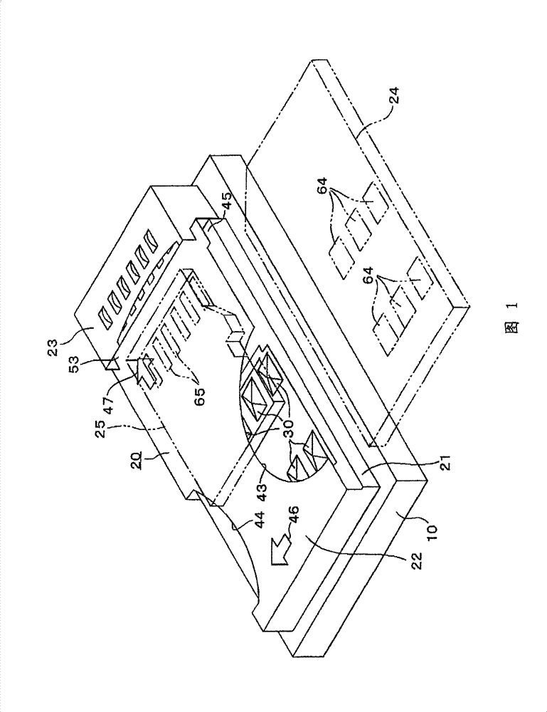
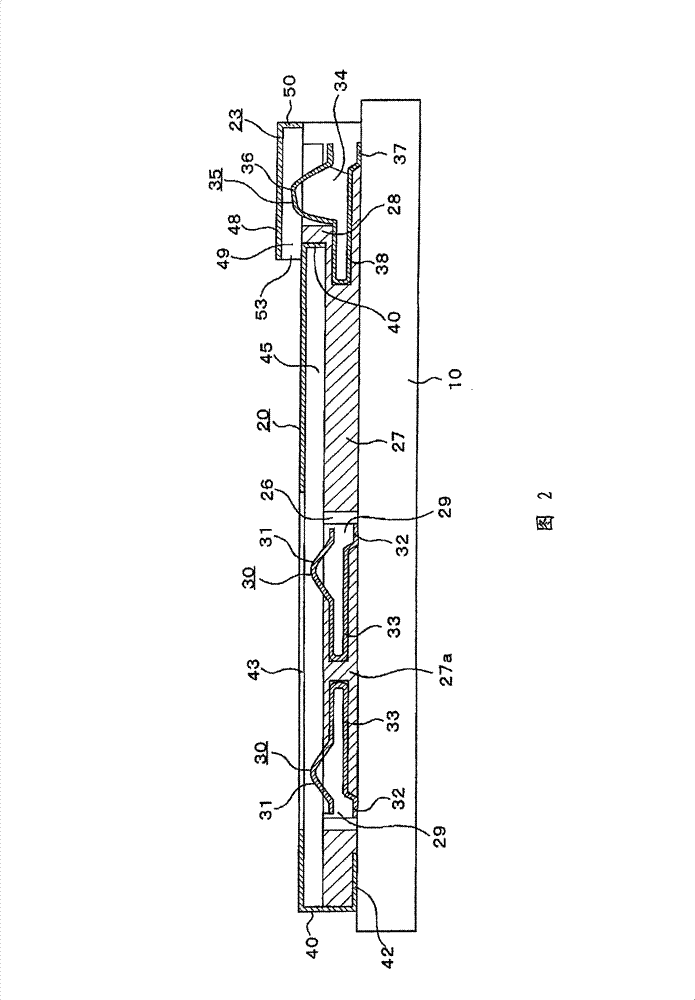
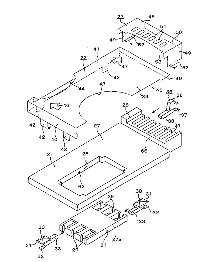
[0048] The following is based on Figure 1 to Figure 4 Example 1 of the present invention will be described.

[0049] The multi-connector 20 of the present invention mounted on the substrate 10 has: a thin plate-shaped body 21, and the first card is covered on the body 21 in such a manner as to hold the first card insertion port 45 inserted into the first memory card 24. The conductive cover 22 for the second card covers the conductive cover 23 for the second card on the end of the conductive cover 22 for the first card so as to hold the second card insertion port 53 inserted into the second memory card 25 .

[0050] The above-mentioned main body 21 is made of a rectangular insulating thin plate such as plastic, and has approximately the same size as the first memory card 24, only slightly larger. A rectangular fitting hole 26 is formed in the center of the main body 21 , and a second connection main body 28 is integrally formed on one short side of the main body 21 to form a...

Embodiment 2

[0065] In Embodiment 1, one conductive cover 23 for a second card is provided on the conductive cover 22 for a first card, and the second memory card 25, which is one type of card, is slidably inserted and removed. However, it is not limited thereto. If the size of the second memory card 25 is smaller than that of the first memory card 24, as Figure 5 As shown, the second connection body 28a and the second connection body 28b can be set on the two ends of the first connection body 27, and the second connection body 28a and the second connection body 28b cover and install the second body respectively. The conductive cover 23a for a card and the conductive cover 23b for a 3rd card slide the conductive cover 22 for a 1st card, and insert and remove the 2nd memory card 25a and the 3rd memory card 25b so that it may slide.

Embodiment 3

[0067] In Embodiment 1, one second card conductive cover 23 is provided on the first card conductive cover 22, and the second memory card 25, which is one type of card, is slidably inserted and removed. In Embodiment 2, the first connecting body 27 is provided with a second connecting body 28a and a second connecting body 28b on both ends of the first connecting body 27, on which the conductive cover 23a for the second card and the third card are respectively covered and installed. The second memory card 25a and the third memory card 25b are inserted and removed by sliding on the first card conductive cover 22 using the conductive cover 23b.

[0068] However, it is not limited thereto. In terms of card size, when the first memory card 24>the second memory card 24a>the third memory card 24b, as Image 6As shown, the above-mentioned body 21 has a first connection body 27, a second connection body 28a connected to the first and one side of the first connection body, and a side of...


PUM


Abstract

The invention provides a composite connector which reduces occupied portion of a substrate caused by a plurality of memory cards related to the carried substrate. The composite connector of the invention has at least a card insertion opening where a first and a second memory card (24, 25) can be plugged on a body (21). The body (21) has a first body (27) for connection and a second body (28) for connection connected with an edge of the first body (27) for connection. On the first body (27) for connection, a first card conductive cover (22) is covered by way of forming a first card insertion opening (45) and on the second body (28) for connection, a second card conductive cover (23) is covered by way of forming a second card insertion opening (53). Outer side surface of the first card conductive cover (22) is used as a slide surface of the second memory card (25) so that the slide surface faces the second card insertion opening (53).

Description

technical field [0001] The present invention relates to a multi-connector for memory cards capable of supporting various types of memory cards of different sizes and shapes and reducing the occupied area of ​​a mounting substrate as much as possible. Background technique [0002] Figure 7 , Figure 8 It is shown that the multi-connector 11 mounted on the substrate 10 is compatible with various types of memory cards having different sizes and shapes (Patent Document 1). [0003] Figure 7 In the composite connector 11 shown, on the main body 12, the lower layer connector 13 and the upper layer connector 14, which are both inserted and removed in the horizontal direction, form a two-layer overlapping structure, and the first memory card is inserted and removed on the lower layer connector 13. 15. On the upper connector 14, insert and remove the second memory card 16 in a direction perpendicular to the first memory card 15. When the first memory card 15 and the second memory...

Claims


Application Information

Patent Timeline
Patent Type & Authority Patents(China)
IPC IPC(8): H01R12/71H01R27/00H01R27/02G06K7/00
Inventor 上原省吾江尻孝一郎
Owner SMK CO LTD
Learn More