
Cable coil putting device

A pay-off device and cable reel technology, which is applied in the directions of transportation and packaging, delivery of filamentous materials, thin material processing, etc., can solve the problems of personal injury, damage to cables, waste of manpower and material resources, etc., and achieve high work efficiency and low cost. Low, simple structure effect

Inactive Publication Date: 2009-11-18
中冶东北建设有限公司电气安装工程公司
View PDF0 Cites 10 Cited by
  • Summary
  • Abstract
  • Description
  • Claims
  • Application Information

AI Technical Summary

Problems solved by technology

[0003] In short, the disadvantages of the traditional cable laying method are: waste of manpower and material resources, easy to cause personal injury, and may damage the cable.

Method used


Image

  • Cable coil putting device
  • Cable coil putting device

Examples


Embodiment Construction

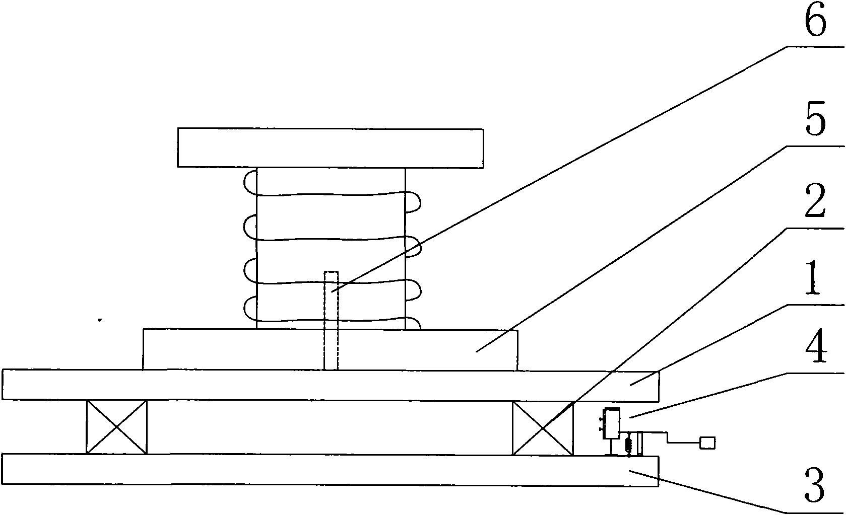
[0013] See figure 1 , The cable reel pay-off device is composed of an upper chassis 1, a lower chassis 3, a rolling bearing 2, and a speed control device 4. A rolling bearing 2 is provided between the upper chassis 1 and the lower chassis 3, and a speed control is provided at the outer edge of the rolling bearing 2. Device 4, the speed control device 4 is located between the upper chassis 1 and the lower chassis 3, this device can artificially control the rotation speed of the cable reel, avoiding the loss caused by the shedding of the cable due to excessive tension. The steel pipe 6 that prevents the cable tray 5 from moving is welded vertically with the upper chassis 1 at the upper center position.

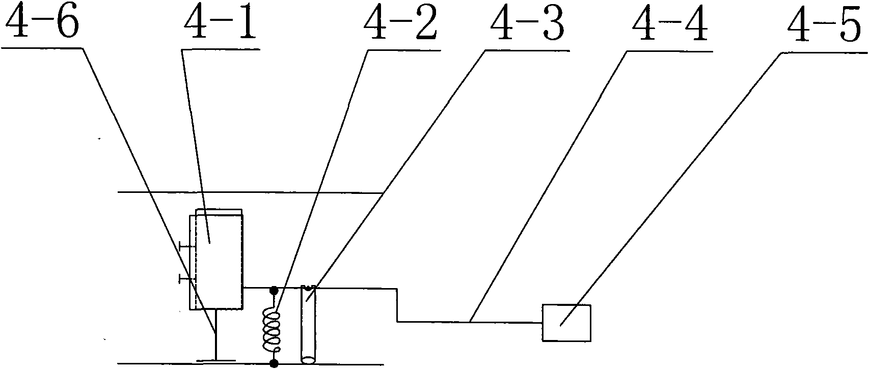
[0014] See figure 2 , speed control device 4 is made up of rubber brake pad 4-1, return spring 4-2, pole 4-3, control rod 4-4, pedal 4-5, support rod 4-6, rubber brake pad 4- 1 Connect the pedal 4-5 through the control rod 4-4, the lower part of the control rod 4-4 is provide...


PUM


Abstract

The invention relates to a cable coil putting device in the field of agricultural electric instrument engineering construction. The cable coil putting device comprises an upper chassis, a lower chassis, a rolling bearing and a speed control device, wherein the rolling bearing is arranged between the upper chassis and the lower chassis, the speed control device is arranged at the outer edge of the rolling bearing and arranged between the upper chassis and the lower chassis, and a steel pipe capable of preventing a cable coil from moving is welded in the center of the upper chassis in the direction perpendicular to the upper chassis. Compared with the prior art, the invention has the advantages of simple structure, low cost, high working efficiency and labor and material saving. The cable coil is hung by a crane to put on the cable coil putting device and can be held by one person while controlling the rotating speed of the cable coil so as to avoid a cable falling phenomenon because of great pulling force.

Description

technical field [0001] The invention relates to a cable reel pay-off device in the construction field of building electrical instrumentation engineering. Background technique [0002] Cable laying is one of the most important tasks for electrical instrumentation construction enterprises. In the prior art, laying power cables is usually lifted by a crane to level the cable reel. Two or more people hold the cable reel, and the cable reel passes through the crane by pulling force The hook rotates to rotate. At the same time, the crane has been occupied until the cable is finished. Sometimes the pulling force of the cable is too large, so that the cable reel rotates too fast, and the person holding the cable reel cannot control the rotation speed of the cable reel, so that the cable falls off from the cable reel, and may cause personal injury and damage to the cable. [0003] In short, the disadvantages of the traditional cable laying method are: waste of manpower and material...

Claims


Application Information

Patent Timeline
IPC IPC(8): B65H49/18B65H63/00
Inventor 程玉所
Owner 中冶东北建设有限公司电气安装工程公司
Learn More