
Fixing device in brick

A technology of fixing devices and brick bodies, applied in the direction of building components, architecture, building construction, etc.

Inactive Publication Date: 2009-11-18
BEIJING XINXUANSHIWEI TECH
View PDF0 Cites 9 Cited by
  • Summary
  • Abstract
  • Description
  • Claims
  • Application Information

AI Technical Summary

Problems solved by technology

[0002] Generally, there is no connecting device inserted in the brick body of the prior art, but in order to make the building of the brick body made of building materials firm, it is necessary to insert a connecting device in the brick body so that two adjacent brick bodies can be fixed. , but there is no such content in the prior art

Method used


Image

  • Fixing device in brick
  • Fixing device in brick
  • Fixing device in brick

Examples


Embodiment Construction

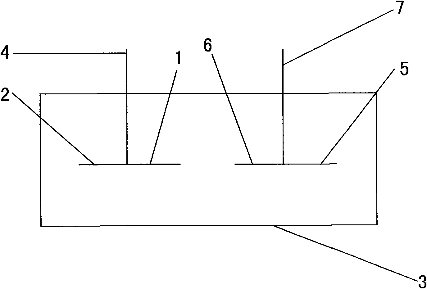
[0032] refer to figure 1 It is a device diagram of the present invention.

[0033] Wherein 1 is a "T" shaped right blocking device embedded in the brick body, which is used to prevent the access device in the brick body from falling off in the brick body.

[0034] Wherein 2 is the " T " shape left blocking device embedded in the brick body, which is used to prevent the access device in the brick body from falling off in the brick body.

[0035] Wherein 3 is brick body, is used for accepting a connecting device, is used for making connecting device and another brick body advance and connect.

[0036] Wherein 4 is the protruding device of " D " sub-shaped connecting device, and this protruding device protrudes from the outer surface of brick body.

[0037] Wherein 5 is the second " T " font right blocking device embedded in the brick body, which is used to prevent the access device in the brick body from falling off in the brick body.

[0038] Wherein 6 is the second "T" shap...


PUM


Abstract

The invention relates to a fixing device in a brick. A connecting device is inserted into the brick, and one part of the connecting device, which is in the brick, is provided with at least one T-shaped stopping device, and the stopping device can prevent the connecting device inserted in the brick falling off from the brick.

Description

technical field [0001] The invention belongs to the field of building materials, in particular to a fixing device in a brick body. Background technique [0002] Generally, there is no connecting device inserted in the brick body of the prior art, but in order to make the building of the brick body made of building materials firm, it is necessary to insert a connecting device in the brick body so that two adjacent brick bodies can be fixed. , but there is no such content in the prior art. [0003] The present invention aims to solve the problem of how to fix the connecting device and the brick body when the connecting device is provided in the brick body. Contents of the invention [0004] The technical problem to be solved by the present invention is to provide a super firm fixing device with the brick body, so that the insertion device and the brick body can be fixed, so that the brick body connected to the insertion device can be permanently fixed with the adjacent bric...

Claims


Application Information

Patent Timeline
Patent Type & Authority Applications(China)
IPC IPC(8): E04B1/41E04C1/00
Inventor 李辰宇
Owner BEIJING XINXUANSHIWEI TECH
Learn More