Oil and gas separating device

A separation device, oil and gas technology, applied in separation methods, dispersed particle separation, engine lubrication, etc., can solve problems such as insufficient separation of oil and gas, and achieve the effects of avoiding oil and gas channeling, close contact, and efficient oil return

Inactive Publication Date: 2009-11-18
CHERY AUTOMOBILE CO LTD
View PDF10 Cites 7 Cited by
  • Summary
  • Abstract
  • Description
  • Claims
  • Application Information

AI Technical Summary

Problems solved by technology

[0003] The purpose of the present invention is to provide an oil-gas separation device for a valve cover to solve the problem of insufficient oil-gas separation in the current oil-gas separation device

Method used


Image

  • Oil and gas separating device
  • Oil and gas separating device
  • Oil and gas separating device

Examples


Embodiment 1

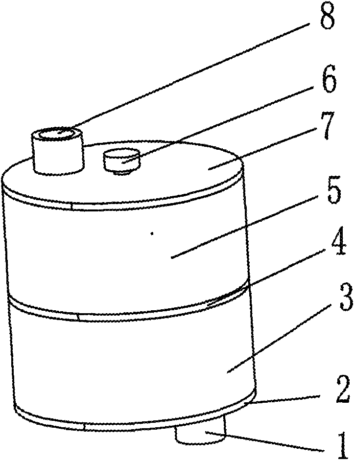
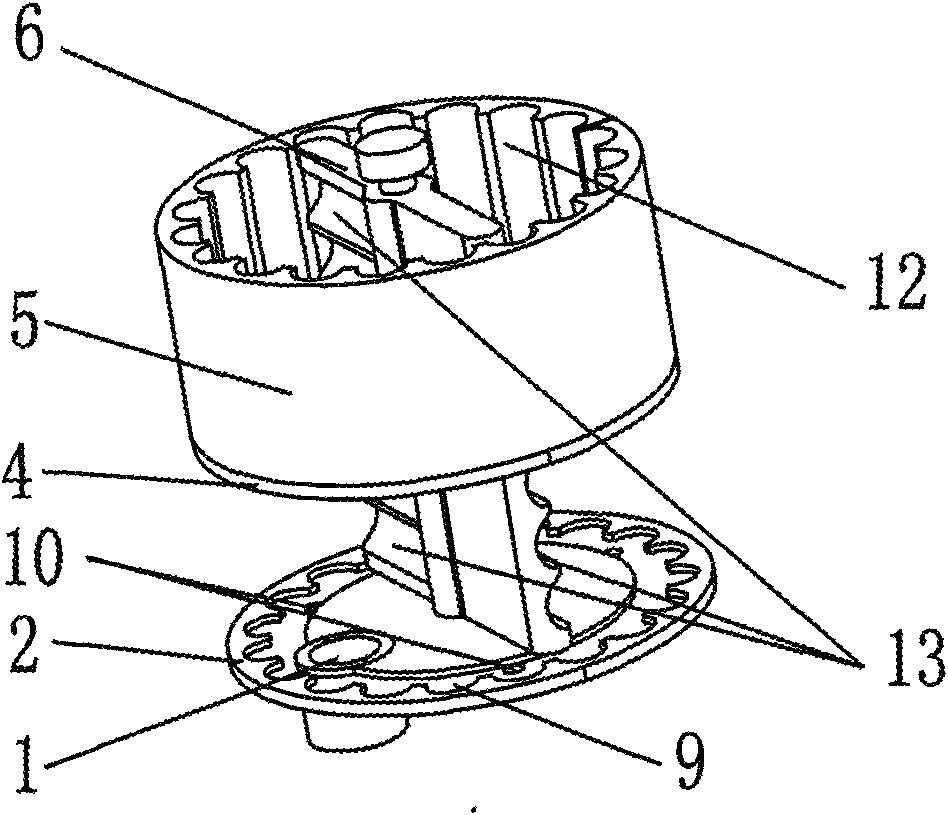
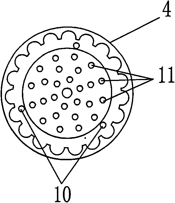
[0014] Example 1, such as figure 1 , 2 As shown in , 3, an oil-gas separation device includes a bottom plate 2 with an oil-gas inlet 1 and an oil return hole 10, a housing and a built-in rotor blade 6, and a cover plate 7 with an oil-gas outlet 8. The housing is divided into a first-level housing 3 and a second-level housing 5. The rotor blades 6 are also divided into upper and lower levels, and a partition 4 is arranged in the middle; the partition 4 is provided with a hole array 11 and Oil return hole.

Embodiment 2

[0015] Embodiment 2, in order to make the oil condense and adhere to the casing, the inner surfaces of the primary casing 3 and the secondary casing 5 are provided with tooth grooves 12 . All the other are with embodiment 1.

Embodiment 3

[0016] Embodiment 3, in order to make the oil condense on the rotor blades and flow to the casing to collect, the windward side of the rotor blades 6 is provided with radial oil guide grooves 13 . All the other are with embodiment 1 or 2.


PUM


Abstract

An oil and gas separating device comprises an oil and gas inlet, a soleplate of an oil returning hole, a shell, a built-in rotor vane, and a cover plate with an oil and gas outlet; the oil and gas separating device is characterized in that the shell is divided into two stages of upper and lower: a stage-one shell and a stage-two shell; the rotor vane is also divided into an upper stage and a lower stage; a screen is arranged between the two stages; and the screen is provided with a hole array and an oil returning hole. The internal surfaces of the stage-one shell and the stage-two shell are provided with tooth spaces respectively. One weather surface of the rotor vane is provided with a radial oil-guiding trough. The soleplate is also provided with a stepped zonal oil returning trough; and the oil returning holes are uniformly arranged in the zonal oil returning trough. As the staged centrifugal separation and screen separation and the tooth space structure which leads the oil to be agglomerated and bonded in the shell are adopted, the oil and gas separation effect is reinforced, and the oil and gas separating device is applicable to the oil and gas separation of valve chamber cover of the engine.

Description

technical field [0001] The invention relates to an oil-gas separation device, in particular to an oil-gas separation device for an engine valve chamber cover. Background technique [0002] At present, a labyrinth is commonly used to separate the oil and gas in the valve chamber cover of an automobile engine, and makes it go around a baffle plate or a perforated array, so that the oil condenses and adheres, and the gas flows out through the labyrinth. Chinese patent application number CN200510061317.7 discloses a labyrinth oil-gas separation device. In this design, part of the oil and gas in the oil and gas separation space flows away before it collides with the baffle, resulting in insufficient condensation of the oil and insufficient oil and gas separation. Contents of the invention [0003] The object of the present invention is to provide an oil-gas separation device for a valve cover to solve the problem of insufficient oil-gas separation in the current oil-gas separa...

Claims


Application Information

Patent Timeline
Patent Type & Authority Applications(China)
IPC IPC(8): F01M11/08B01D45/00
Inventor 易敏
Owner CHERY AUTOMOBILE CO LTD
Why Eureka
Try Eureka