
Method for producing infrared signal of sending terminal of infrared ray corresponding emission device

A technology of infrared signal and generation method, applied in the direction of optical device exploration, etc., can solve the problems of cracking the protective net, power monitoring, inconvenient daily maintenance, etc., to achieve the effect of easy maintenance and improved reliability

Active Publication Date: 2009-11-18
NINGBO HENGBO TELCOMM
View PDF0 Cites 10 Cited by
  • Summary
  • Abstract
  • Description
  • Claims
  • Application Information

AI Technical Summary

Problems solved by technology

[0003] 1. Since the high-frequency pulse signal sent by the transmitter is simple and universal, there is no identification code function. If you replace the installed transmitter with the same type of transmitter, move it to the receiver at a short distance, and let the replaced transmitter also generate After the high-frequency pulse signal is aimed at the receiving end, the original protective net formed by the sending end and the receiving end will be cracked;
[0004] 2. At present, the sending end of the known infrared radiation device cannot collect various information related to the actual work of the sending end, nor can it be transmitted to the host, so it brings inconvenience to daily maintenance
This mainly includes: it is impossible to identify and transmit the ambient temperature of the infrared radiation, so that it is impossible to identify the occurrence of fire in advance; it cannot identify and transmit the abnormal situation of high or low power supply voltage, so it is impossible to monitor the power supply of the radiation ; The light intensity cannot be identified and transmitted, so it is impossible to avoid false alarms caused by strong light interference;
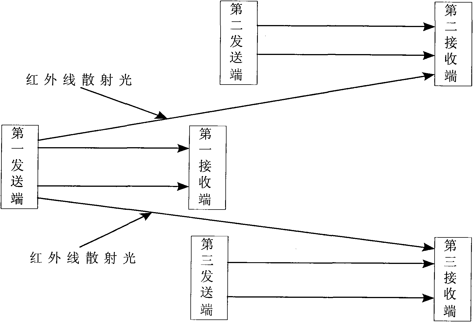
[0005] 3. At present, when the known infrared radiation devices are installed at a short distance, there are disadvantages of mutual influence, such as the attached figure 1 As shown, the infrared scattered light sent by the first sending end will be received by the second receiving end and the third receiving end
In these solar-powered infrared radiation devices, how to solve the problem of continuous power supply caused by long-term rainy weather is closely related to the amount of power consumed by the radiation, and some will be unable to do what they want, and cannot be promoted in many places around the clock

Method used


Image

  • Method for producing infrared signal of sending terminal of infrared ray corresponding emission device
  • Method for producing infrared signal of sending terminal of infrared ray corresponding emission device
  • Method for producing infrared signal of sending terminal of infrared ray corresponding emission device

Examples


Embodiment Construction

[0029] The present invention will be further described in detail below in conjunction with the accompanying drawings and embodiments.

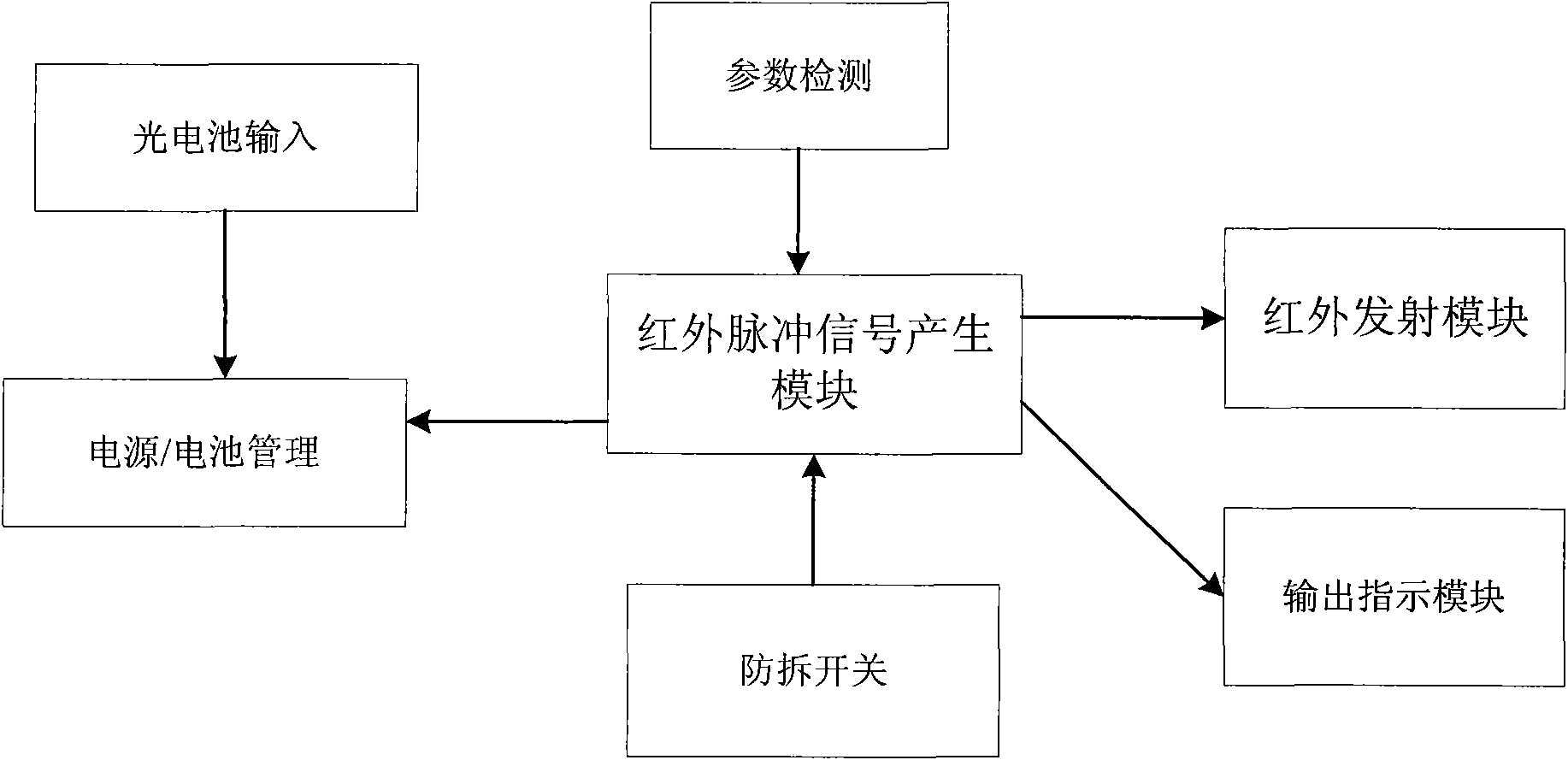
[0030] Such as figure 2 As shown, the sending end of the infrared radiation device of the present invention includes an infrared pulse signal generating module, an infrared emitting module, a photocell input module, a power supply / battery management module, a parameter detection module, an output indication module, and a tamper switch, wherein the photocell input module is generally As a solar power supply module, it provides power for the sending end of the infrared radiation device; the power supply / battery management module manages the charging and discharging of the rechargeable battery, controls the voltage of the rechargeable battery within the normal working range, and provides work for the sending end of the infrared radiation device power supply; the infrared pulse signal generation module is used to generate infrared pulse signals a...


PUM


Abstract

The invention relates to a method for producing an infrared signal of a sending terminal of an infrared ray corresponding emission device, and the sending terminal of the infrared ray corresponding emission device comprises an infrared pulse signal generating module and an infrared emission module. The infrared ray corresponding emission device is characterized in that the sending terminal is provided with only address information and also comprises a parameter detection module used for detecting status messages of the sending terminal, and generates the infrared signal according to the following steps: (1) first, an aequilate primary high-frequency pulse signal is generated; (2) pulse amplitude modulation is carried out on the primary high-frequency pulse signal to generate a secondary pulse signal; (3) the status messages and the address information are loaded onto the secondary pulse signal by adopting a way of pulse phase modulation, so that a third pulse signal is obtained; (4) the generated third pulse signal is transmitted to the infrared emission module and then sent to a receiving terminal. Compared with the prior art, the mutual interference of signals among sending terminals and receiving terminals of a plurality of infrared ray corresponding emission device can be avoided by the method.

Description

technical field [0001] The invention relates to a method for generating an infrared signal at the sending end of an infrared beam-to-radiation device. Background technique [0002] Currently known active intrusion detectors generally use infrared radiation devices, and their working principle is to generate a high-frequency pulse signal of equal width by the sending end (here, the high-frequency pulse signal generated by the sending end can avoid the interference of sunlight ), and then convert the high-frequency pulse signal into an infrared light signal through the infrared transmitting module for transmission. When the infrared light signal is not received, the receiving end immediately sends it to the alarm host through the connection line or wirelessly, and finally the host implements the alarm. This infrared radiation device mainly has the following defects: [0003] 1. Since the high-frequency pulse signal sent by the transmitter is simple and universal, there is no...

Claims


Application Information

Patent Timeline
Patent Type & Authority Applications(China)
IPC IPC(8): G01V8/12
Inventor 童君玉王全斌叶利民
Owner NINGBO HENGBO TELCOMM
Learn More