Chirp grating tuner based on magnetoconstriction

A magnetostrictive and chirped grating technology, applied in the field of optical communication, can solve the problems of slow response speed of chirped Bragg grating and achieve the effect of dynamic dispersion compensation

Inactive Publication Date: 2009-11-18
HARBIN INST OF TECH
View PDF0 Cites 10 Cited by
  • Summary
  • Abstract
  • Description
  • Claims
  • Application Information

AI Technical Summary

Problems solved by technology

[0006] The purpose of the present invention is to solve the problem of slow response speed in tuning chirped Bragg gratings by using temperature tuning technology, and provides a chirped grating tuning device based on magnetostriction

Method used


Image

  • Chirp grating tuner based on magnetoconstriction
  • Chirp grating tuner based on magnetoconstriction
  • Chirp grating tuner based on magnetoconstriction

Examples


specific Embodiment approach 1

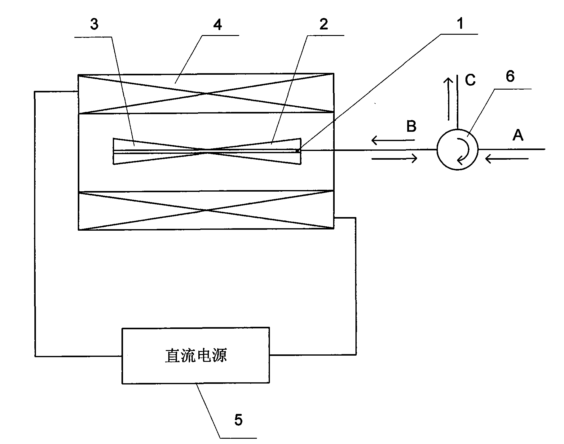
[0013] Specific implementation mode one: the following combination figure 1 , figure 2 and image 3 Describe this embodiment, this embodiment comprises chirped grating 1, positive magnetostrictive film 2, negative magnetostrictive film 3, spiral tube 4 and DC power supply 5,

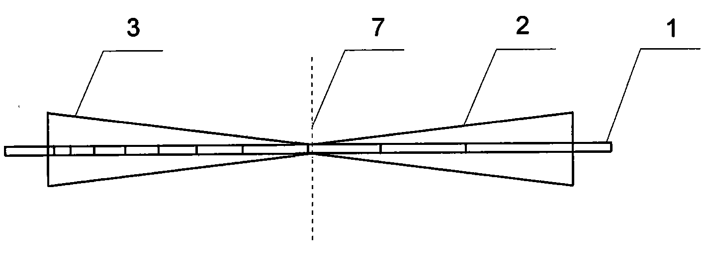
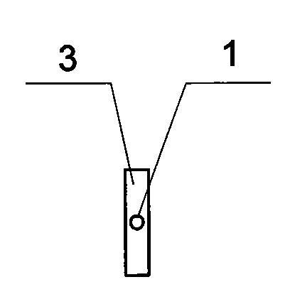
[0014] The chirped grating 1 is coated with a positive magnetostrictive film 2 and a negative magnetostrictive film 3, the positive magnetostrictive film 2 and the negative magnetostrictive film 3 are pentahedrons whose cross section is an isosceles triangle, and the positive magnetostrictive film 2 and the negative magnetostrictive film 3 are mirrored along the vertical line 7 of the axis of the chirped grating 1, and the symmetry line of the positive magnetostrictive film 2 and the symmetry line of the negative magnetostrictive film 3 are all aligned with the axis of the chirped grating 1 coincide, the apex of the positive magnetostrictive film 2, the apex of the negative magnetostrictive film 3 and...

specific Embodiment approach 2

[0026] Specific embodiment two: The difference between this embodiment and embodiment one is that the material of the positive magnetostrictive film 2 is selected with a magnetostriction coefficient of 300×10 -6 TbFe 2 , the material of the negative magnetostrictive film 3 is selected with a magnetostrictive coefficient of -300×10 -6 SmFe 2 , the other components and connections are the same as those in Embodiment 1.

specific Embodiment approach 3

[0027] Embodiment 3: The difference between this embodiment and Embodiment 1 is that the chirped grating 1 adopts a high-reflectivity grating with a reflectivity above 95%, and other components and connections are the same as Embodiment 1.


PUM

PropertyMeasurementUnit
reflectanceaaaaaaaaaa

Abstract

The invention discloses a chirp grating tuner based on magnetoconstriction, belonging to the field of optical communication. The chirp grating tuner based on magnetoconstriction aims to solve the problem that response speed is low when chirp bragg grating is tuned with thermal tuning technology. The chirp grating of the invention is plated with a positive magnetostrictive film and a negative magnetostrictive film, wherein, the positive magnetostrictive film and the negative magnetostrictive film are both pentahedron whose cross section is isoceles triangle, and the positive magnetostrictive film and the negative magnetostrictive film are arranged along the perpendicular bisector of the axial line of the chirp grating in a mirror image mode; the symmetric lines of the positive magnetostrictive film and the negative magnetostrictive film are both in superposition with the axial line of the chirp grating, and the top of the positive magnetostrictive film and the top of the negative magnetostrictive film are in superposition with the central point of the chirp grating; the length of triangle hemline of the positive magnetostrictive film is 3.5 to 5 times of the diameter of the chirp grating, and the thickness of the positive magnetostrictive film is 1.1 to 1.5 times of the diameter of the chirp grating; chirp grating plated with the positive magnetostrictive film and the negative magnetostrictive film is arranged in a helix tube, and two ends of the helix tube loop are respectively connected with the positive pole and the negative pole of a direct current supply. The invention is used for chromatic dispersion compensation in optical communication.

Description

technical field [0001] The invention relates to a chirped grating tuning device based on magnetostriction, which belongs to the field of optical communication. Background technique [0002] In recent years, with the development of optical communication, network capacity is also expanding. The single-wavelength transmission rate of practical optical communication networks has reached the order of 10Gbit / s or even 40Gbti / s, and dispersion has become a non-negligible factor for the degradation of optical signal transmission quality and the increase of bit error rate. Practice has proved that whether it is a backbone network or a metropolitan area network, the dispersion compensation of the optical transmission system is a necessary unit to maintain the transmission quality. At the same time, the diversification and configurable functions of supporting devices related to optical communication networks enable ordinary point-to-point wavelength division multiplexing communication...

Claims


Application Information

Patent Timeline
Patent Type & Authority Applications(China)
IPC IPC(8): G02F1/01
Inventor 冷劲松刘彦菊代勇波李建军
Owner HARBIN INST OF TECH
Why Eureka
Try Eureka